


LT8302
18
8302fb
For more information
www.linear.com/LT8302
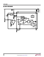
applicaTions inForMaTion
Design Example
Use the following design example as a guide to designing
applications for the LT8302. The design example involves
designing a 5V output with a 1.5A load current and an
input range from 8V to 32V.
V
IN(MIN)
= 8V, V
IN(NOM)
= 12V, V
IN(MAX)
= 32V,
V
OUT
= 5V, I
OUT
= 1.5A
Step 1: Select the transformer turns ratio.
N
PS
<
65V – V
IN(MAX)
– V
LEAKAGE
V
OUT
+
V
F
V
LEAKAGE
= Margin for transformer leakage spike = 15V
V
F
= Output diode forward voltage = ~0.3V
Example:
N
PS
<
65V – 32V – 15V
5V
+
0.3V
=
3.4
The choice of transformer turns ratio is critical in determin-
ing output current capability of the converter. Table 2 shows
the switch voltage stress and output current capability at
different transformer turns ratio.
Table 2. Switch Voltage Stress and Output Current Capability vs
Turns Ratio
NPS
V
SW(MAX)
at
V
IN(MAX)
(V)
I
OUT(MAX)
at
V
IN(MIN)
(A)
DUTY CYCLE (%)
1:1
37.3
0.92
14-40
2:1
42.6
1.31
25-57
3:1
47.9
1.53
33-67
Clearly, only N
PS
= 3 can meet the 1.5A output current
requirement, so N
PS
= 3 is chosen as the turns ratio in
this example.
Step 2: Determine the primary inductance.
Primary inductance for the transformer must be set above
a minimum value to satisfy the minimum switch-off and
switch-on time requirements:
L
PRI
≥
t
OFF(MIN)
•N
PS
• V
OUT
+
V
F
(
)
I
SW(MIN)
L
PRI
≥
t
ON(MIN)
• V
IN(MAX)
I
SW(MIN)
t
OFF(MIN)
= 350ns
t
ON(MIN)
= 160ns
I
SW(MIN)
= 0.87A
Example:
L
PRI
≥
350ns • 3 • 5V
+
0.3V
(
)
0.87A
=
6.4µH
L
PRI
≥
160ns • 32V
0.87A
=
5.9µH
Most transformers specify primary inductance with a toler-
ance of ±20%. With other component tolerance considered,
choose a transformer with its primary inductance 40% to
60% larger than the minimum values calculated above.
L
PRI
= 9µH is then chosen in this example.
Once the primary inductance has been determined, the
maximum load switching frequency can be calculated as:
f
SW
=
1
t
ON
+
t
OFF
=
1
L
PRI
•I
SW
V
IN
+
L
PRI
•I
SW
N
PS
• V
OUT
+
V
F
(
)
I
SW
=
V
OUT
•I
OUT
• 2
η
• V
IN
•D


