10
dc2442af
DEMO MANUAL DC2442A
Figure 7. PC to RAM Button Transfers Data Programmed
from the GUI to the LTC4282 Volatile Registers
Update registers contents by clicking or typing to change
the desired registers, then selecting the “PC to RAM” but-
ton in the top toolbar. LTpowerPlay writes changes to the
updated registers.
Note that programming the registers in the LTC4282 should
generally be done while the part is in the sequenced-
down state—with the pass transistor turned off. Most of
the registers have immediate control over their respec-
tive chip functions, and changing them while the part is
sequenced-up will have unpredictable and adverse effects.
It is recommended to sequence-down before updating
configuration register settings, LTpowerPlay implements
limits to writing some registers, based upon the device
state, and will pop-up warnings when necessary.
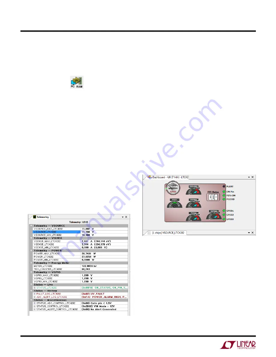
Right of center in LTpowerPlay is the Telemetry pane,
displaying read-only information contained in the status
registers of the selected part. The GUI periodically polls
the I
2
C bus and updates the Telemetry contents in real
time, along with a user-friendly interpretation of the bits.
In the upper right corner of LTpowerPlay is the Chip
Dashboard pane, displaying a graphical representation of
the part status in a friendly, easy-to-understand format.
The meter in the upper left of the panel displays the static
input energy to the card in watts. The small dials in the
center of the Input Energy Meter display the energy used
in kJoules. The V
SOURCE
meter displays the voltage at the
SOURCE pin of the LTC4282, which is the same as V
OUT
.
The INPUT meter displays the voltage input at the V
DD
pin
of the LTC4282. V
SENSE
indicates the input current derived
by dividing the voltage measured across the sense resistor
divided by the value of the sense resistor. The Power Meter
displays the SOURCE voltage multiplied by the current
sense voltage and scaled to indicate the power in watts.
V
GPIO3
displays the voltage at GPI03 when it is configured
as an analog input. The FET status annunciators show the
status of the pass MOSFETs as described in the FET-BAD
Fault section of the data sheets. GPI01, GPI02, and GPI03
show the status of the general purpose input/output pins.
Figure 8. LTpowerPlay Telemetry
Figure 9. LTpowerPlay Dashboard
SOFTWARE CONTROL WITH LTpowerPlay


