14
dc1962cf
DEMO MANUAL DC1962C
aDvanceD Demo BoarD operations
Up to eight DC1962C boards can be cascaded to control
up to 112 independent power supplies. The number of
boards is limited by an I/O expander chip that has three
address pins, allowing 8 different combinations. This
setup demonstrates the coordinated fault responses and
accurate time base shared across multiple power system
managers.
Procedure:
1. Stack the boards side-by-side by plugging JP1 of one
board into JP2 of another DC1962C board.
2. Ensure different slave address settings for each of the
boards. The address of each DC1962C board is deter-
mined by pins A2, A1 and A0 of the DIP switch JP1 on
the backside of the board. The setting must be unique
for each board in the array.
3. Plug in the +12V V
IN
power into one of the boards as
shown in Figure 10. Only one +12V power source is
allowed.
setup proceDure for multiBoarD arrays
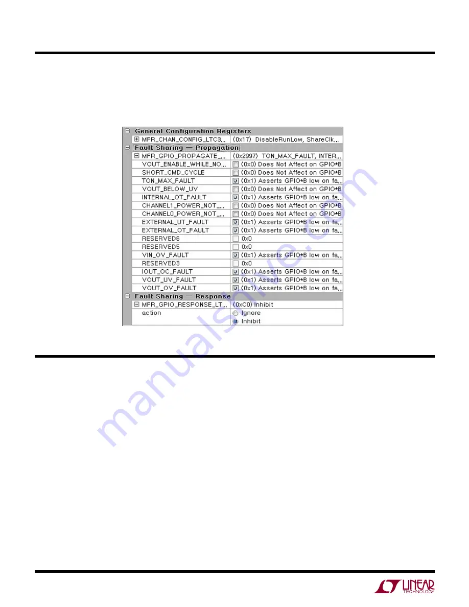
The two LTC3880 channels can be uniquely configured
and any fault can be propagated or not. Since the LTC3880
GPIO pins are tied together, a fault on CH0 may be used to
turn off CH1. This is achieved by setting the appropriate
MFR_GPIO_PROPAGATE command code and the MFR_
GPIO_RESPONSE command to “inhibit.”
Содержание DC1962C
Страница 19: ...18 dc1962cf DEMO MANUAL DC1962C DC1962C Details Bottom...
Страница 23: ...22 dc1962cf DEMO MANUAL DC1962C Schematic Diagram...
Страница 24: ...23 dc1962cf DEMO MANUAL DC1962C Schematic Diagram...
Страница 25: ...24 dc1962cf DEMO MANUAL DC1962C Schematic Diagram...
Страница 26: ...25 dc1962cf DEMO MANUAL DC1962C Schematic Diagram...
Страница 27: ...26 dc1962cf DEMO MANUAL DC1962C Schematic Diagram...
Страница 28: ...27 dc1962cf DEMO MANUAL DC1962C Schematic Diagram...
Страница 29: ...28 dc1962cf DEMO MANUAL DC1962C Schematic Diagram...


