2
dc1785bfa
DEMO MANUAL DC1785B
quick start proceDure
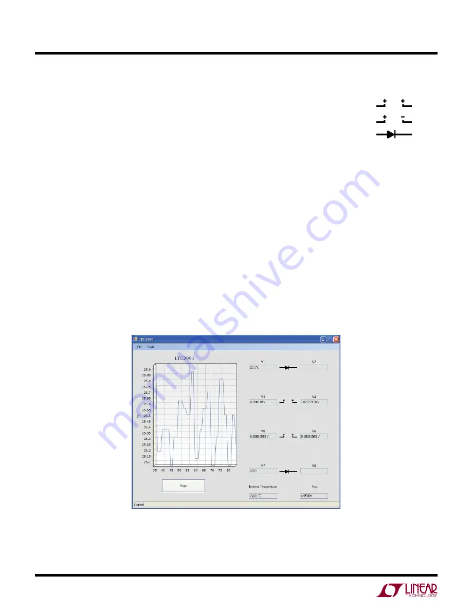
Figure 2. Software Screenshot
Connect the DC1785B to a DC590 USB Serial Controller
using the supplied 14-conductor ribbon cable. Connect the
DC590 to host PC with a standard USB A/B cable. Run the
evaluation software supplied with DC590 or downloaded
from http://www.linear.com/software. The correct program
will be loaded automatically. Click the COLLECT button to
start reading the input voltage. Details on software features
are documented in the control panel’s help menu.
SoFtwarE SEt-UP
The DC1785B software is designed to give the user ac-
cess to all LTC2991 functionality and features. There are
several options that may be accessed both through right
and left clicks.
Input Settings
By default, all eight inputs are set as single-ended. This may
be modified by either left clicking the input type picture to
cycle through the options or right clicking the picture to
bring up a list of options and left clicking to select.
The legend for each input type icon is included below.
Single-Ended (default)
Differential
Diode Temperature
Input sampling can also be turned on and off by left click-
ing the label of the corresponding input. When an input
is off, the values box below the label will be shaded and
the value will stop updating.
Graph Settings
By default, the QuikEval software will graph V1. To begin
graphing a different input, left click the values box of the
input to be graphed.
To pan the graph, hold down the right mouse button while
hovering over the graph and move the mouse in the direc-
tion of desired motion. The graph will cease to auto-scroll
after a pan has be initiated, to reactivate the auto-scroll
double left click anywhere on the graph.


