background image

4

DC1333afa

DEMO MANUAL DC1333A

Information  furnished  by  Linear  Technology  Corporation  is  believed  to  be  accurate  and  reliable.  

However, no responsibility is assumed for its use. Linear Technology Corporation makes no representa-

tion that the interconnection of its circuits as described herein will not infringe on existing patent rights.

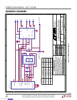
Figure

 3. 

LTC

2640

 Schematic

 Diagram

SCHEMATIC DIAGRAM

5

5

4

4

3

3

2

2

1

1

D

D

C

C

B

B

A

A

H

D

R

2

X

7

-0

7

9

-MO

L

E

X

-C

LT

C

2640 

LZ

12

L

T

C

2

6

40 

H

M

12

U1

LT

C

2640 

H

Z

1

2

-A

L

T

C

 P

A

R

T

#

*

-B

LT

C

2640

 -

 L

M

1

2

-D

A

ssy 

T

a

b

le

*

1

0

_C

LR

/R

E

F

_S

E

L

R3

J

P1

4.

99

K

4.

99

K

NO

NO

J

P1

NO

NO

J

P1

*

*

A

D

C

1333A

-A

/B

/C

/D

Tuesday,

 S

ept

em

ber

 23,

 2008

1

1

HEL

EN

9/

12/

07

Leo 

C

hen

9/

12/

07

S

in

g

le

 1

2

/1

0

/8

-B

it S

P

I V

o

u

t D

A

C

LT

C

2640-

LM

12/

LZ

12/

H

M

1

2

/H

Z

1

2

S

IZE

SC

AL

E

:

C

A

G

E

 CO

DE

D

W

G

 NO

R

EV

S

H

E

E

T

OF

F

IL

EN

AM

E

:

TI

TL

E

C

O

N

T

RA

CT

 N

O

.

APPR

O

V

A

L

S

D

A

TE

DRAW

N

CHECKED

APPRO

VED

ENG

INEER

DESI

G

NER

T

E

CHNO

L

O

G

Y

1630 

M

cC

ar

thy

 B

lv

d.

M

ilp

ita

s

, C

A

 95035

P

hone:

 (

408)

432-

1900

Fax

(408)

434-

0507







































































































































































































































































































































































































































E7

_C

LR

/R

E

F

_S

E

L

S

D

I

J

1

1

2

3

4

5

6

7

8

9

10

11

12

13

14

V

UNRE

G

5V

GND

S

C

K

/S

C

L

MIS

O

CS

M

O

S

I/

S

D

A

GND

E

E

S

D

A

E

E

V

C

C

E

E

S

C

L

E

E

G

N

D

GND

NC

J

P1

1

2

3

R2

4.

99

K

R1

4.

99

K

C2

0

.1uF

E3

G

ND

E1

V

CC

U1

L

T

C

2

6

4

0

1

3

2

7

4

6

8

5

_C

S

/LD

S

DI

S

CK

V

O

UT

GND

REF

_

CL

R/

RE

F

_

S

E

L

VCC

E2

RE

F

_C

S

/LD

R3

O

PT

C1

0

.1uF

E5

G

ND

S

CK

Arra

y

EE

PR

OM

U

2

2

4

LC

025-

I/

S

T

5

6

7

4

8

3

2

1

S

DA

S

CL

WP

G

ND

V

CC

A

2

A

1

A

0

E4

V

O

U

T

E6

G

ND

R4

4.

99

K

Downloaded from

Arrow.com.

Downloaded from

Arrow.com.

Downloaded from

Arrow.com.

Downloaded from

Arrow.com.

Содержание DC1333A

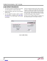
Страница 1: ...trademark of Linear Technology Corporation All other trademarks are the property of their respective owners BOARD PHOTO performance After evaluating with Linear Technology s software the digital signals can be connected to the end application s processor Design files for this circuit board are available at http www linear com demo DC1333A Figure 1 DC1333A Connection Diagram DAC CONNECTIONS RIBBON ...

Страница 2: ...am will be loaded automatically Options are available to display the DAC output in voltage hex code or decimal count Additionally the reference voltage may be changed to reflect an actual measured value such that the output voltage matches the theoreti cal output voltage The reference mode may be changed from internal reference to external reference Features may be periodically added to the softwa...

Страница 3: ...re provided on the row of turret posts at the edge of the board GROUNDING AND POWER CONNECTIONS Power VCC Normally the DC1334A is powered by the DC590 controller VCC can be supplied to the 5V turret howeverthepowersupplyontheDC590mustbedisabled Refer to the DC590 Quick Start Guide for more details on this mode of operation Grounding Three ground posts are provided Downloaded from Arrow com Downloa...

Страница 4: ... 23 2008 1 1 HELEN 9 12 07 Leo Chen 9 12 07 Single 12 10 8 Bit SPI Vout DAC LTC2640 LM12 LZ12 HM12 HZ12 SIZE SCALE CAGE CODE DWG NO REV SHEET OF FILENAME TITLE CONTRACT NO APPROVALS DATE DRAWN CHECKED APPROVED ENGINEER DESIGNER TECHNOLOGY 1630 McCarthy Blvd Milpitas CA 95035 Phone 408 432 1900 Fax 408 434 0507 E7 _CLR REF_SEL SDI J1 1 2 3 4 5 6 7 8 9 10 11 12 13 14 VUNREG 5V GND SCK SCL MISO CS MO...

Страница 5: ...333A REVISION HISTORY BOARD REV DATE DESCRIPTION PAGE NUMBER A 04 16 Corrected Part s Removed BOM 1 Downloaded from Arrow com Downloaded from Arrow com Downloaded from Arrow com Downloaded from Arrow com Downloaded from Arrow com ...

Страница 6: ... EXCEPT TO THE EXTENT OF THIS INDEMNITY NEITHER PARTY SHALL BE LIABLE TO THE OTHER FOR ANY INDIRECT SPECIAL INCIDENTAL OR CONSEQUENTIAL DAMAGES The user assumes all responsibility and liability for proper and safe handling of the goods Further the user releases LTC from all claims arising from the handling or use of the goods Due to the open construction of the product it is the user s responsibil...

Отзывы: