DC1123A QUICK START GUIDE
2
eliminating the need for external compensation
components.
The LTC3562 offers two different types of ad-
justable step-down regulators. The two Type A
regulators (R600A, R400A) can have the feed-
back voltage adjusted from 425mv to 800mv in
25mv increments. The two Type B regulators
(R600B, R400B) can have the output voltages
adjusted through I
2
C control from 600mv to
3.775V in 25mv increments.
QUICK START PROCEDURE
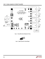
Using short twisted pair leads for any power
connections and with all loads and power sup-
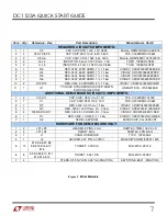
plies off, refer to Figure 1 for the proper meas-
urement and equipment setup.
NOTE.
When measuring the input or output voltage ripple, care
must be taken to avoid a long ground lead on the oscilloscope
probe. Measure the input or output voltage ripple by touching the
probe tip directly across the VCC or VOUT and GND terminals. See
Figure 2 for proper scope probe technique.
1.
Place jumpers and load settings in the following
positions:
JP1 (RUN600A)
= ON
JP2 (RUN400A)
= ON
Load 1
= Consant Current 50mA
Load 2
= Constant Current 50mA
Load 3
= Constant Current 50mA
Load 4
= Constant Current 50mA
2.
Connect Power Supply PS1 to VIN terminals
and adjust to 4.5 Volts to the demo board, as
shown in Figure 1.
3.
Verify that OUT600A (1.8V) and OUT400A
(1.5V) are operational with proper output volt-
ages.
4.
Once the proper output voltages are estab-
lished, adjust the loads within the operating
range and observe the output voltage regula-
tion, ripple voltage, and efficiency.
5.
Open the Quickstart Software as discribed in the
DC590 Quick Start Guide
6.
Set Jumpers JP1 (RUN400A) and JP2
(RUN600A) to Off Position. Connect Ribbon ca-
ble from DC590 demo circuit to J2. The LTC
3562 demonstation software should pop-up
automatically when the cable is installed.
7.
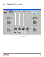
Using the LTC3562 software GUI. See Figure 3.
Set all modes to Burst mode, VOUT 600A to
1.82V, VOUT 600B to 3.3V, VOUT 400A to
1.51V and VOUT 400B to 1.2V. Set all loads to
50mA. Check Auto Update buttons. Click on
Enable All button.
8.
Once the proper output voltages are estab-
lished, adjust the loads within the operating
range and observe the output voltage regula-
tion, ripple voltage, and efficiency.
9.
Using the LTC3562 software GUI. Set all modes
to Pulse Skip mode, VOUT 600A to 1.82V,
VOUT 600B to 3.3V, VOUT 400A to 1.51V and
VOUT 400B to 1.2V. Set all loads to 50mA.
10.
Once the proper output voltages are estab-
lished, adjust the loads within the operating
range and observe the output voltage regula-
tion, ripple voltage, and efficiency.
11.
Using the LTC3562 software GUI. Set all mod-
es to Forced Burst mode, VOUT 600A to 1.82V,
VOUT 600B to 3.3V, VOUT 400A to 1.51V and
VOUT 400B to 1.2V. Set all loads to 50mA.
12.
Once the proper output voltages are estab-
lished, adjust the loads within the operating
range and observe the output voltage regula-
tion, ripple voltage, and efficiency
13.
Using the LTC3562 software GUI. Set all mod-
es to LDO mode, VOUT 600A to 1.82V, VOUT
600B to 3.3V, VOUT 400A to 1.51V and VOUT
400B to 1.2V. Set all loads to 50mA.


