QUICK START GUIDE FOR DEMONSTRATION CIRCUIT 1317A-A
ACTIVE RESET ISOLATED 48V INPUT TO 3.3V @30A DC/DC POWER CONVERTER
6
Rcs1
0.015R
+Vin
Cu1
4.7u
R23 1.2k
R24
39K
Vu1
R15
115k
R20
174k
C10
0.1u
CS
Q1
D10
B
A
T
7
6
0
C15
2.2nF, 2kV
R28
442k
R22
13.3k
Si7430
PA0861.004
GND
8
SD
7
MaxDC
5
FB=1.23V
2
Comp
1
Rosc
3
Vr=2.5V
6
Blank
9
Delay
12
OC
11
Sync
4
Isense
10
PGND
13
Out
14
Vin
15
Sout
16
U1
LT1952-1
R33
470k
C13
.47u
SS
SS
R26
220R
R30
1.2k
R14
33K
C23
1uF
Vfb
Vfb
R13
22K
C
o
1
2
x
1
0
0
u
F
R27
470
R38
18.2K
R35
82.5k
R34
4.75k
C19
1uF
C16
0.22uF
C17
10n
CS
SS
3
Vcc
1
FB
4
Opto
6
GND
2
Comp
5
U4
LT4430
Cin
2x2.2uF
+Vin
D5
PDZ10B
Vu1
D2
BAS516
R11
82k
1
6
+Vin
R1
2.2R
R32
332k
L1
PA1671.650
Q2
HAT2165
Q3
D6
B0540W
R8
2.2R
Q12
BC856T
D3
Q10
PBSS8110
+Vb
+Vb
L2
1.5mH
U6
PS2801-1
T1
D11
BAS516
GND
+Vout
+
C
sy
s
4
7
0
u
F,
6
.3
V
C24
47p
C9
100p
C25
10n
R49
2.2R
Q13
Si2325
D14
BAS516
R45
10k
+Vr2
+Vr2
R50
2.2R
D17
BAS516
R53
200
2, 3
4, 5
7, 8
9, 10, 11
C33
0.1u
C34
0.22uf
R54
4.7
-Vin
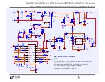
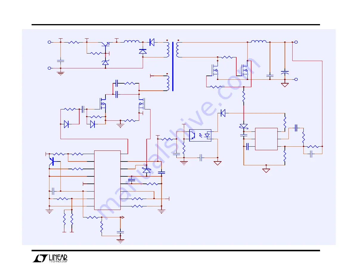
Demo Board DC1317A-A schematic
NOTE:
This schematic shows only the components required for operation of -A version
of DC1317A demo board.
All optional components of DC1317A demo board have been removed.
Also, all zero-ohm resistors have been replaced with wires.
Please consult the full DC1317A-A schematic to decide if any of the optional
components should be included in your design.


