2) Set Up Your ScanGauge
Your new ScanGauge must first be set up so
that it may report accurate information about
your vehicle.
To access the Basic Setup Options, follow
the sequence shown to the right. For more
detailed setup instructions and a complete
explanation of each of the setup parameters,
please refer to the ScanGauge User Manual.
Use the lower buttons to adjust the
currently selected setup parameter
Use the upper buttons to move to the next or
previous setup parameter
Displays the currently selected setup parameter
Package Contents
•
ScanGauge
•
6-ft J1939/J1708 Cable
•
Velcro
®
Strips
•
Quick Start Guide
Front
A. Function/Selection Button
B. Function/Selection Button
C. Function/Selection Button
D. Function/Selection Button
E. Home Button
F. LCD Display Screen
Back
G. J1939/J1708 Connection Plug
Side
H. Optional J1939/J1708 Connection
Plug or unit daisy chain interface
Front
Side
Back
A
B
C
D
E
H
G
F
ScanGauge Layout
HOME Screen
<SCAN
<TRIP
GAUGE>
MORE>
<SETUP
<DISPLAY
MORE>
FILLUP>
<
>
<
>
DISTANCE
MILES
Setup Parameter Display
Options
Distance Units
DISTANCE
Miles, Kilometers
Fuel Units
FUEL UNITS
Gallons, Liters
Temperature Units
TEMP UNITS
Fahrenheit (˚F), Celsius (˚C)
Pressure Units
PRESSURE UNITS
PSI, KPA, MM, IN
Tank Size
TANK SIZE
Adjustable in 1 Gallon/Liter Increments
Currency type
CURRENCY
$, £, ¥,
元
,€
Advanced Settings
ADV SETTINGS
For an explanation of the Advanced Setting Options,
please refer to the user manual and ScanGauge.com
5.
Connect the small end of the cable
Plug the small end of the cable into the back or side of the
ScanGauge.
6.
Turn the vehicle on.
Start your vehicle or turn the ignition to the ON position.
Plug the ScanGauge Plug Into The Diagnostic Connector.
While inserting in the plug, you may have to rotate to the plug to align the connector pins.
Once the pins are aligned, push firmly on the plug to complete the connection.
Once connected with the vehicle running or the ignition in the ON position, your ScanGauge
will display the Connecting Screen, and then quickly switch to the Home Screen.
When the Home Screen is displayed, your ScanGauge is connected and has established
communication with your vehicle’s computer.
Connecting...
<TRIP
MORE>
Connecting Screen
<SCAN
<TRIP
GAUGE>
MORE>
Home Screen
Up to 10
seconds
7.
Proceed to setup.
If it does not stop saying “Connecting...” or the screen goes blank after 60 seconds,
refer to Troubleshooting section in the ScanGauge User Manual.
Small end of the cable
connects to your ScanGauge.
1) Quick Start Installation
1.
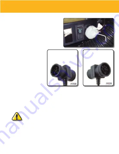
Locate the Diagnostic Connector
The connector is generally located under
the dash at the fire wall on the driver
side and is usually protected by a plastic
cover. To remove the protective cover,
you must push the cover while turning
counter clockwise, then pull to remove it.
2.
Determine Plug Type
The universal plug
included with your
ScanGauge is compatible
with both the J1939 (9pin)
and J1708 (6-pin)
diagnostic port. Match the
end of the plug to the
connector, but do not plug
it in at THIS time.
3.
Locate a Place For The ScanGauge.
You can use the sticky-back Velcro
®
supplied with the ScanGauge to attach it to the
location you have chosen.
DO NOT mount the ScanGauge over an air bag cover where it could be
propelled by a deploying airbag.
4.
Route The Cable.
Route the cable from the ScanGauge to your vehicle’s diagnostic connector. Be sure
Keep the cord from interfering with the pedals or operating controls of the vehicle.
6-pin
connects to vehicles
that use the J1708 protocol
9-pin
connects to vehicles
that use the J1939 protocol
Typical J1939/J1708 protective cover


