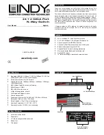
LED Status Indicators
Type
LED
Status
Description
Steady Green
Power is on
System Power
Off
Power is off
Steady Green
A valid link is
established
Flashing Green
Data packets
transmitted
Port 1-24
One LED per
port (10/100)
LINK/ACT
Off
No link is established
Steady Green
Port running at 10Mbps
10M
Off
No 10Base-T link is
established
Steady Green
Port running at
100Mbps
100M
Off
No 100Base-T link is
established
Steady Green
Port running at
1000Mbps
1000M
Off
No 1000Base-T link is
established
Green
Data packets
transmitted
Port 25,26 Four
LED’s per port
(10/100/1000)
ACT
Off
No link is established
Installation
Operating Environment
This switch must be installed and operated within the specified
limits of the operating temperature and humidity as detailed in the
Specifications
section
Do not place objects on top of the unit. Do not obstruct any vents at
the sides of the unit
Do not position the switch in direct exposure to the sun or near any
heat source such as a heater, radiator etc.
Prevent water and moisture entering the unit. If necessary use a
dehumidifier to reduce humidity
Connecting network devices
This switch features Auto MDI/MDI-X RJ-45 ports for easy connection to
other network devices using either a straight-through or crossover type
connecting cable.
1.
Connect one end of the network cable to the RJ-45 port on the front
panel and connect the other end of the network cable to the RJ-45
port on the network device.
2.
Follow the same procedure to connect each of the RJ-45 ports on
the switch.
3.
The network cables must comply with EIA/TIA 568 specifications
and the
Category 5 standard for 100Mbps data transmission
and at least
Category 5e for 1000Mbps transmission
.
4.
The maximum length of any Ethernet segment is 100m. For
combined installations the 90m + 10m rule should be regarded
(90m with solid core installation cable + 10m for the patch cables).
Radio Frequency Energy, Certifications
FCC Certifications
This equipment has been tested and found to comply with the limits for a
Class A digital device, pursuant to part 15 of the FCC Rules. These limits
are designed to provide reasonable protection against harmful
interference when the equipment is operated in a commercial
environment.
This equipment generates, uses, and can radiate radio frequency energy
and, if not installed and used in accordance with the instruction manual,
may cause harmful interference to radio communications.
Operation of this equipment in a residential area is likely to cause
harmful interference in which case the user will be required to correct the
interference at their own expense.
This device complies with Part 15 of the FCC Rules. Operation is subject
to the following two conditions: (1) this device may not cause harmful
interference, and (2) this device must accept any interference received;
including interference that may cause undesired operation.
CE Certification
This equipment complies with the requirements relating to
electromagnetic compatibility, EN 55024 and EN55022 class A for ITE,
EN61000-3-2/-3 the essential protection requirement of Council Directive
89/336/EEC on the approximation of the laws of the Member States
relating to electromagnetic compatibility.
LINDY No. 25003
www.lindy.com
1
st
Edition March 2005


