


Page 18
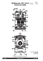
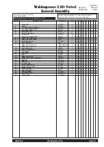
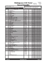
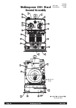
Weldanpower 230+
IMA 572F
GROUND TEST PROCEDURE
Note:
This procedure is for ‘machines as built’ many modifications
could have taken place over the life of a particular machine, so
details of this procedure may need to be ‘adjusted’ to suit these
modifications.
For prompt service contact your local authorised Lincoln field
service shop.
The insulation resistance values listed below are from Australian
Standard AS1966.2.
1.
Ensure engine is stopped.
2.
Remove welding leads and disconnect any auxiliary
equipment cables.
3.
Disconnect the battery leads from the battery and unplug
battery voltage regulator plug (if fitted).
4.
Place jumpers across all four (4) terminals of each o the
field bridge rectifier [D2] and the welding output bridge
rectifier [D1] (ie. positive, negative and 2off A terminals).
5.
Unplug PCB connectors (x2), jumper leads No. 200B, 201A
75, 76 and 77 together in the PCB plug.
Unplug leads from idler solenoid PCB.
6.
Ensure all leads and clips are isolated from each other and
the machine frame.
7.
Place switch ‘S3’ in STOP position (petrol only) and ‘S4’ in
HIGH position.
8.
Field circuit test:
Connect one lead of the mega tester to
the front panel ground stud and the other lead to lead No.
200A at rectifier [D2]. Apply the test. (Min. resistance 1M
Ω
)
9.
Auxiliary circuit test:
Connect one lead of the mega tester
to the front panel ground stud and the other lead to the
‘active’ terminal of one of the 240V auxiliary outlets. Apply
the test. (Min. resistance 1M
Ω
)
10.
Welding circuit test:
Connect one lead of the mega tester
to the front panel ground stud and the other lead to the
electrode output stud. Apply the test. (Min. resistance 1M
Ω
)
11.
Auxiliary circuit to welding circuit test:
Connect one
lead of the mega tester to the ‘active’ terminal of one of the
240V auxiliary outlets and the other to the electrode output
stud. Apply the test. (Min. resistance 10M
Ω
)
12.
Auxiliary circuit to field circuit test:
Connect one lead of
the mega tester to lead No. 200A at rectifier [D2] and the
other to ‘active’ terminal of one of the 240V auxiliary outlets.
Apply the test. (Min. resistance 1M
Ω
)
13.
Welding circuit to field circuit test:
Connect one lead of
the mega tester to lead No. 200A at rectifier [D2] and the
other lead to the electrode output stud. Apply the test.(Min.
resistance 1M
Ω
)
14.
Remove all jumpers and reconnect all leads.
This procedure is only suitable for applications using DC
mega testers up to 500V.
WARNING
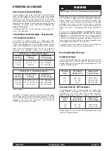
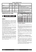
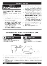
Weldanpower 230+ LN-22 and LN-25 Across the arc connection diagram
ELECTRIC SHOCK can kill
MOVING PARTS can injure
• Do not operate with panels open.
• Disconnect NEGATIVE (-) battery lead before servicing.
• Do not touch electrically live parts.
• Keep guards in place.
• Keep away from moving parts.
• Only qualified personnel should install, use or service this
equipment.
WARNING
N.A. WELDING CABLE MUST BE SIZED FOR CURRENT AND DUTY CYCLE OF APPLICATION.
N.B. USE POLARITY SWITCH TO SET FOR DESIRED ELECTRODE POLARITY, POSITION THE OUTPUT SELECTOR SWITCH TO
THE WIRE FEED (CV) POSITION.
N.C. IF OPTIONAL REMOTE OUTPUT CONTROL IS USED, PLACE OUTPUT CONTROL SWITCH IN “OUTPUT CONTROL REMOTE”
POSITION.
N.D. SET IDLE CONTROL SWITCH TO HIGH IDLE FOR LN-22 AND LN-25 WITHOUT CONTACTOR, SET TO AUTO FOR LN-25 WITH
INTERNAL CONTACTOR.
Содержание WELDANPOWER 230+
Страница 8: ...Page 8 Weldanpower 230 IMA 572F...
Страница 43: ...IMA572F Weldanpower 230 Page 43 NOTES...