F-2
DIMENSION PRINT
POWER WAVE
®
S500CE
(2-12)
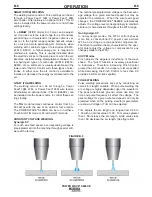
27.
43
22.
4
5
13.
96
6.
00
24.
76
18.
35
Страница 1: ...READ ING THIS MANUAL AND THE SAFETY PRECAUTIONS CON TAINED THROUGHOUT And most importantly think before you act and be careful For use with machines having Code Numbers 11883 Cleveland Ohio 44117 119...
Страница 2: ...KER WEARERS SHOULD CONSULT WITH THEIR DOCTOR BEFORE OPERATING Read and understand the following safety highlights For additional safety information it is strongly recommended that you purchase a copy...
Страница 3: ...Never simultaneously touch electrically hot parts of electrode holders connected to two welders because voltage between the two can be the total of the open circuit voltage of both welders 3 i When w...
Страница 4: ...eas Avoid welding near hydraulic lines Have a fire extinguisher readily available 6 b Where compressed gases are to be used at the job site special precautions should be used to prevent hazardous situ...
Страница 5: ...inflammables 4 Des gouttes de laitier en fusion sont mises de l arc de soudage Se prot ger avec des v tements de protection libres de l huile tels que les gants en cuir chemise paisse pan talons sans...
Страница 6: ...ponsibility of the user of the welding equipment to resolve the situation with the technical assistance of the manufacturer In some cases this remedial action may be as simple as earthing grounding th...
Страница 7: ...ommendations Welding Cables The welding cables should be kept as short as possible and should be positioned close together running at or close to floor level Equipotential Bonding Bonding of all metal...
Страница 8: ...ly important when identifying the correct replacement parts CUSTOMER ASSISTANCE POLICY The business of The Lincoln Electric Company is manufacturing and selling high quality welding equipment consumab...
Страница 9: ...Features B 3 Case Front Controls B 3 Case Back Controls B 4 Common Welding Procedures B 5 thru B 7 ________________________________________________________________________________ Accessories Section...
Страница 10: ...x fan on Power Factor Rated Output 95 Input Voltage 10 230 400 460 575 50 60 Hz includes 380V to 415V For voltages higher than 460V or applications outside the European union replace input cord with p...
Страница 11: ...onmentally Hardened 4 F to 104 F 20C to 40C STORAGE TEMPERATURE RANGE Environmentally Hardened 40 F to 185 F 40C to 85C PROCESS GMAW GMAW Pulse FCAW GTAW DC SMAW OUTPUT RANGE AMPERES 40 550A 5 550A 15...
Страница 12: ...bustible surface directly under stationary or fixed electrical equipment that surface shall be covered with a steel plate at least 060 1 6mm thick which shall extend not less than 5 90 150mm beyond th...
Страница 13: ...he input circuit with the recommended super lag fuse or delay type breakers also called inverse time or thermal magnetic circuit breakers Choose input and grounding wire size according to local or nat...
Страница 14: ...with the power source as shown in Figure A 2 SMAW STICK WELDING TIG T TORC RCH K2266 1 K KIT INC NCLUD UDES ES W WORK C CLAMP ADAP APTER A AND ND R REGULATOR ARCLINK POSITIVE WORK CLAMP BACK CONNECTI...
Страница 15: ...k welding from a LF 45 wire feeder can be used with the power source as shown in Figure A 3 ARCLINK POSITIVE WORK PART OF K2394 1 BACK CONNECTIONS ON LF 45 LF 45 K2394 1 ELECTRODE HOLDER KIT K857 2 RE...
Страница 16: ...ding from a LF 45 wire feeder can be used with the power source as shown in Figure A 4 ARCLINK POSITIVE WORK CLAMP BACK CONNECTIONS ON LF 45 LF 45 GUN K470 XX WORK PIECE POWER WAVE S500 CE ARCLINK POS...
Страница 17: ...lt in unsatisfactory weld ing performance Always use the largest welding cables electrode and work that are practical and be sure all connections are clean and tight Note Excessive heat in the weld ci...
Страница 18: ...ur pose The POWER WAVE S500CE has the ability to auto matically sense when remote sense leads are con nected With this feature there are no requirements for setting up the machine to use remote sense...
Страница 19: ...ve electrode polarity This feature can be disabled through the Weld Manager Utility available at www powerwavesoftware com or through the set up menu if a user interface is installed into the power so...
Страница 20: ...esult in arc interference If Sense Leads ARE Used Position the sense leads out of the path of the weld current Especially any current paths common to adjacent arcs Current from adjacent arcs can induc...
Страница 21: ...connect all work leads on one side of the weld joint and all of the work voltage sense leads on the opposite side such that they are out of the current path See Figure A 7 POWER SOURCE 2 POWER SOURCE...
Страница 22: ...in ArcLink control cable connects the power source to the wire feeder The control cable consists of two power leads one twisted pair for digital com munication and one lead for voltage sensing The 5 p...
Страница 23: ...THE FRONT OF THIS OPERATING MAN UAL WARNING SAFETY PRECAUTIONS READ AND UNDERSTAND ENTIRE SECTION BEFORE OPERATING MACHINE POSITIVE OUTPUT NEGATIVE OUTPUT STATUS PROTECTIVE GROUND COOLER WARNING OR C...
Страница 24: ...welding and may also be suitable for basic hard automation applications The POWER WAVE S500CE can be set up in a number of configurations some requiring optional equipment or welding programs RECOMME...
Страница 25: ...the ArcLink platform State of the art power electronics technology yields superior welding capability Electronic over current protection Input over voltage protection F A N fan as needed Cooling fan o...
Страница 26: ...S See Figure B 2 1 ETHERNET 2 GAS INLET OPTIONAL 3 RESERVED FOR FUTURE DEVELOPMENT 4 SYNC TANDEM OPTIONAL 5 REAR ARCLINK OPTIONAL 6 DEVICENET OPTIONAL 7 COOLER OUTPUT POWER PANEL OPTIONAL 8 INPUT POWE...
Страница 27: ...elding mode offers the simplicity of single knob control The machine will select the cor rect voltage and amperage based on the Wire Feed Speed WFS set by the operator BASIC WELDING CONTROLS Weld Mode...
Страница 28: ...G Synergic CV For each wire feed speed a corresponding voltage is preprogrammed into the machine through special soft ware at the factory The nominal preprogrammed voltage is the best aver age voltage...
Страница 29: ...stick outs from 0 50 to 1 25 At very low or high wire feed speeds the adaptive range may be less due to reaching physical limitations of the welding process UltimArc Control adjusts the focus or shape...
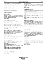
Страница 30: ...ble Twist Mate to Lug Adapter For connection of lugged cable to Twist Mate con nectors 18 457 mm long Order K2176 1 Dual Cylinder Kit Permits side by side mounting of two full size gas cylinders with...
Страница 31: ...length ORDER K2374 1 STICK ELECTRODE HOLDER CABLE AND WORK CABLE ASSEMBLY Includes 200A stick electrode holder welding cable work clamp and Twist Mate adapter ORDER K2394 1 TIG OPTIONS Pro Torch TIG T...
Страница 32: ...king the calibration will not need adjustment However neglected or improp erly calibrated machines may not yield satisfactory weld performance To ensure optimal performance the calibration of output V...
Страница 33: ...and or are unable to perform the Recommended Course of Action safely contact your local Lincoln Authorized Field Service Facility HOW TO USE TROUBLESHOOTING GUIDE Service and Repair should only be per...
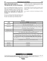
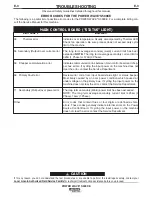
Страница 34: ...eady Green Blinking Green Fast Blinking Green Alternating Green and Red Steady Red Blinking Red Status LED off Meaning Main control board status light and Input control board System OK Power source is...
Страница 35: ...imit of the machine The long term average secondary weld current limit has been exceeded NOTE The long term average secondary current limit is 325A 1 Phase or 575A 3 Phase Indicates communication link...
Страница 36: ...e tripped Typically caused by a fan malfunction or blocked air vent Temporary 337 Precharge Timeout The DC bus voltage was not charged to a certain level at end of precharge If problem persists contac...
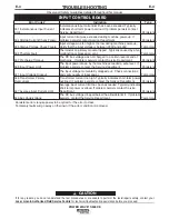
Страница 37: ...1 No Input Power 2 Input voltage is too low or too high 1 Input voltage is too low or too high 2 Thermal Error 3 Secondary current limit has been exceeded see error 54 3a Input control board fault see...
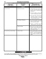
Страница 38: ...proper Shielding Gas 4 Verify weld mode is correct for process 5 Machine calibration 1 Check for proper fan operation Fan should run in a low speed setting when the machine is idle and in a high speed...
Страница 39: ...ult 1 Input voltage may be too low lim iting output capability of the power source 2 The input may be single phase 3 Machine calibration 1 Wire feed problem 2 Loss of or improper Shielding Gas 3 Machi...
Страница 40: ...tion 1 Verify that the correct patch cable or cross over cable is being used refer to local IT department for assistance 1a Verify the cables are fully insert ed into the bulk head connector 1b The LE...
Страница 41: ...It may not be accurate for all machines covered by this manual The specific diagram for a particular code is pasted inside the machine on one of the enclosure panels If the diagram is illegible write...
Страница 42: ...F 2 DIMENSION PRINT F 2 POWER WAVE S500CE 2 12 27 43 22 45 13 96 6 00 24 76 18 35...
Страница 43: ...electrically live parts or electrode with skin or wet clothing Insulate yourself from work and ground No toque las partes o los electrodos bajo carga con la piel o ropa moja da Aislese del trabajo y...
Страница 44: ...e Be und Entl ftung des Arbeitsplatzes Mantenha seu rosto da fuma a Use ventila o e exhaust o para remover fumo da zona respirat ria Turn power off before servicing Desconectar el cable de ali mentaci...
Страница 45: ...ill contact you by the next business day For Non U S Service Email globalservice lincolnelectric com Cleveland Ohio 44117 1199 U S A TEL 1 216 481 8100 For Service in U S and Canada Call 1 888 935 387...