Lincoln Electric LWF-4GS Скачать руководство пользователя страница 10

B-2                                                     

OPERATION                               

B-2


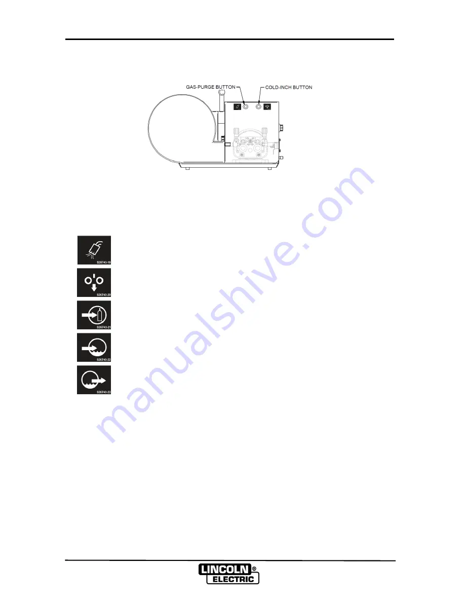
THE COLD-INCH AND GAS-PURGE BUTTON 


FIGURE B.3-BUTTON 


Open the left panel, you can see the cold-inch and gas-purge button as shown in FIGURE B.3.


SYMBOL DESCRIPTIONS 


SYMBOL 

DESCRIPTION


GAS PURGE BUTTON 


COLD INCH BUTTON 


GAS INLET 


COOLING WATER INLET 


COOLING WATER OUTLET 

Содержание LWF-4GS

Страница 1: ...g and cutting equipment is designed and built with safety in mind However your overall safety can be increased by proper installation and thoughtful operation on your part DO NOT INSTALL OPERATE OR RE...

Страница 2: ...conductor causes localized Electric and Magnetic Fields EMF Welding current creates EMF fields around welding cables and welding machines 1 b EMF fields may interfere with some pacemakers and welders...

Страница 3: ...the proper filter and cover plates to protect your eyes from sparks and the rays of the arc welding or observing open arc welding The headshield and filter lens should conform to ANSI Z87 I standards...

Страница 4: ...ork cables connected to the building framework or other locations away from the welding area increase the possibility of the welding current passing through lifting chains crane cables or other altern...

Страница 5: ...___________________ Date of Purchase ______________________ Whenever you request replacement parts for or information on this equipment always supply the Information you have recorded above Read this...

Страница 6: ...ntrol Cable A 2 Option Extension Cables A 2 Welding Gun A 2 Connection Diagram LWFTM Wire Feeder to Lincoln Power Source A 2 Operation Section B Installing Drive Rolls B 1 Loading the Wire Spool B 1 T...

Страница 7: ...TH DEPTH WEIGHT LWFTM 4GS 400mm 230mm 620mm 14 1kg Note Please only use this wire feeder with specified power sources otherwise no output will be produced and the machine may be damaged SAFETY PRECAUT...

Страница 8: ...nects to gas flow regulator Shielding gas such as CO2 Ar and blend gas can be used and the gas pressure cannot be more than 0 7 MPa CONTROL CABLE The control cable is included in the interconnection c...

Страница 9: ...n the retainer on the spindle and put on the welding wire spool see FIGURE B 2 Next replace the retainer and tighten Release the pressure handles and lift the pressure arms insert the welding wire int...

Страница 10: ...RGE BUTTON FIGURE B 3 BUTTON Open the left panel you can see the cold inch and gas purge button as shown in FIGURE B 3 SYMBOL DESCRIPTIONS SYMBOL DESCRIPTION GAS PURGE BUTTON COLD INCH BUTTON GAS INLE...

Страница 11: ...s Clean the dust and metal particles and find out the cause Check if the diameter of the outlet suits the wire diameter If not suitable erratic arc or metal particles will occur Check if the end of th...

Страница 12: ...CH BUTTON 5 4 3 6 2 1 VOLTAGE REGULATOR FEED MOTOR CURRENT REGULATOR 5 k 5 k 4 7 k 10 k 221 GAS PURGE BUTTON 2 5 k P1 P2 P3 P4 GAS VALVE Shanghai Lincoln Electric Company No195 Lane 5008 HuTai Road Sh...

Отзывы: