6
INSTALLATION
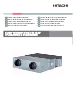
PRISM 2400 STATIONARY FAN
INSTALLATION OF PRISM
2400 STATIONARY FAN
WITH TELESCOPIC 5 FT
EXTRACTION ARM
K1656-9 Prism 2400 Stationary Fan Includes:
• Prism 2400 Stationary Fan
• (2) Bolts, M8x1.25, about 0.75” (20mm) long
• (2) Bolts, M8x1.25, about 2.5” (65mm) long
• (4) Washers, M8
K1655-10 Telescopic 5 FT Extraction Arm includes:
• Telescopic Arm, Assembled
• Flexible hose, (2) 8” Rubber seals for connection to fan
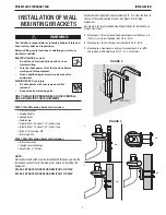
Install wall mounting brackets as detailed in the section titled
“INSTALLATION OF WALL MOUNTING BRACKETS”
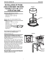
Position the tapered connection flange (See Figure 9, item C) on the
wall mounting brackets. Use the (2) 0.75” long and (2) 2.5” long
bolts with washers supplied with the fan to secure the Prism 2400
Stationary Fan (See Figure 9, item B) and the tapered connection
flange to the wall mounting brackets. Tighten all bolts securely to
make a good seal on the inlet of the fan.
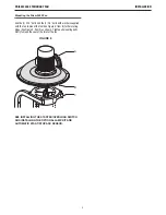
Position one of the 8” rubber seals supplied with the Telescopic
5 FT Arm on the largest part (8” diameter) of the tapered connection
flange. Roll the bottom of the rubber seal up, and slide one end of
the 4 ft. flexible hose (supplied with the arm) up over the tapered
connection flange until it butts up against the folded side of the
rubber seal. Fold the rubber seal down over the hose.
Secure the connection with one 8” hose clamp. Apply the second 8”
rubber seal and the other end of the flexible hose to the top of the
telescopic arm tube.
SEE THE TELESCOPIC 5 FT EXTRACTION ARM
OPERATOR’S MANUAL FOR DETAILS ON COMPLETING
THE INSTALLATION OF THE ARM.
INSTALLING WITH OPTIONAL PRISM WALL MOUNT
The Prism Wall Mount Filter Unit can be installed to filter the
exhausted air before it is recirculated or exhausted outside.
The K1654-4 Prism Wall Mount Filter Unit Includes:
• Complete Filter Unit, with filter installed and inlet(s) and outlet(s)
sealed
• Reducer, 6”-8”
• 8” Connection hose, 4 ft. long
• (2) 8” Hose Clamps
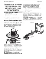
Fit the small (6” diam.) side of the 6”-8” Reducer (See Figure 10,
item B) over the outlet of the Prism 2400 Fan (See Figure 10, item A);
be sure to slide the Reducer all the way over the rubber seal. Secure
with three sheet-metal screws through the reducer into the plastic-
molded fan outlet.
Fit one end of the 8” Connection hose (See Figure 10, item C) over the
larger side of the 6”-8” Reducer. Secure with one 8” hose clamp.
SEE PRISM WALL MOUNT MANUAL FOR COMPLETION OF
THE INSTALLATION PROCEDURE.
FIGURE 10
8” DIAMETER
CONNECTION HOSE
8” HOSE CLAMP
REDUCER 6.3” - 8”
B
A
C
FIGURE 9
A
B
D
C
Содержание K1656-9
Страница 19: ...THIS PAGE INTENTIONALLY LEFT BLANK ...


