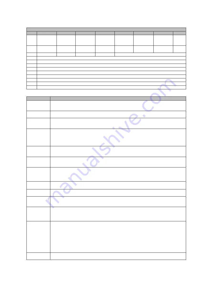
Lincoln Electric K14140-1 Скачать руководство пользователя страница 10

English  

English 

10

I/O Format 

I/O from Welder to Master 

Cyclic I/O  From Welder to Master 
Byte  B7 

B6 

B5 

B4 

B3 

B2 

B1 

B0 

0 Misc 

Module 
Fault 

Wire Stick 

WC Fault 

Water 
Fault 

WD Fault 

Gas Fault 

Touch 
Sense 

Arc 
Detect 

1  


Anybus 
Fault 

PM Limit 

PM Fault 

Weld 
Complete 

Limit Error 


Weld Sequencer Current State 

3  

Voltage Feedback, Low Byte  (In Volts with 1 implied decimal places) 

Voltage Feedback, High Byte 

Current Feedback, Low Byte (In Amps with 1 implied decimal places) 

Current Feedback, High Byte 

Wire Drive Motor Current, Low Byte (Signed value In Amps with 2 implied decimal places) 

Wire Drive Motor Current, High Byte 

10 

Wire Feed Speed Feedback, Low Byte  

11 

Wire Feed Speed Feedback, High Byte 


I/O Bit Description to Master  

Item 

Description 

Arc Detect 

A True value indicates sufficient arc voltage and arc current have been detected.  Arc voltage and 
arc current levels are addicted to mode. When there is no longer sufficient Arc current and Arc 
voltage then go to False. 

Touch Sensed  A True value indicates that the Touch Sense detected a short between the work piece and the 

electrode.  

Gas Fault 

A True value indicates there is a failure in the gas controller. If a fault occurs the weld Power Wave 
will turn the output off and welding will not be possible until the problem is corrected and the fault 
is cleared. 

WD Fault 

Asserted when there is a fault in the Wire Drive. This fault occurs also when Shutdown input is 
open on the external I/O connector Ref. Power Wave / Power Feed Wire Feeder Interconnections 
section describing External I/O Connector in the Operator’s Manual. If a fault occurs the weld 
Power Wave will turn the output off and welding will not be possible until the problem is corrected 
and the fault is cleared. 

Water Fault 

True when Arclink Water Cooler reports an error. If a fault occurs the weld Power Wave will turn 
the output off and welding will not be possible until the problem is corrected and the fault is 
cleared. 

WC Fault 

True when there is a Weld Controller fault.  Refer to “Troubleshooting” in the Operator’s Manual 
for a list of possible errors. If a fault occurs the weld Power Wave will turn the output off and 
welding will not be possible until the problem is corrected and the fault is cleared. 

Wire Stick 

True value indicates that after the welding output is turned off there is a short between the 
electrode and the workpiece. This will stay true until the welding output is turned on and the error 
is cleared or if a Touch Sense Command is asserted and the short has been cleared. This check 
is disabled by default and be enabled using the option “Enable Wire Stick Check”. 

Misc Module 
Fault 

True value indicates that a module, like the Advance Module, STT Switch, High Frequency Switch 
has a fault. 

Limit Error 

Indicates that one of the Welding Job Parameters is out of limits. This will not stop welding 
process. 

Weld 
Complete 

Indicates that the weld has completed (subsequent to the trigger going false) including any 
downslope, crater, burnback and postflow times. Goes false when the next weld begins (trigger 
going true). 

PM Fault 

This bit is used to indicate that the Production Monitoring object is faulty, a common cause is that 
the Production Monitoring object detected a limit error while welding and the Out of limit action 
was set to Alarm Latch. This faulty condition must be cleared before welding; toggling the PM Flt 
Reset bit to the welder should clear this condition. 

PM Limit 

This bit is used to indicate that the Production Monitoring (PM) object detected a limit error. This 
bit is clear automatically when the trigger input goes on or when the PM Flt Reset bit to the welder 
goes on.  
This bit is basically just a status item indicating a PM limit fault occurred, but depending on how 
PM is configured, other behavior can occur when this bit goes on. If PM is set to Fault System, 
then PM will shut the Power Source output off automatically when a limit error occurs, this will 
cause the LGA sequencer to fault and stop welding. If PM is set to Alarm Latch and a limit error 
occurs, then the PM object will fault after the weld is over and welding can not resume until the PM 
fault is cleared (see the PM Fault bit). 

Anybus Fault 

This bit is used to indicate that the Anybus module has a fault. This includes selecting a job with 
invalid Workpoint or Trim units, or selecting an invalid Job number. 

Содержание K14140-1

Страница 1: ...IM3056 11 2017 REV01 LGA Interface OPERATOR S MANUAL ENGLISH Lincoln Electric Bester Sp z o o ul Jana III Sobieskiego 19A 58 263 Bielawa Poland www lincolnelectric eu ...

Страница 2: ...NET K14140 2 LGA Interface DEVICENET K14140 3 LGA Interface PROFIBUS conforms to the following directives 2014 30 CE and has been designed in compliance with the following standards EN 60974 10 2014 15 11 2017 Piotr Spytek Operations Director Lincoln Electric Bester Sp z o o ul Jana III Sobieskiego 19A 58 263 Bielawa Poland 07 11 ...

Страница 3: ...reference record in the table below your equipment identification information Model Name Code Serial Number can be found on the machine rating plate Model Name Code Serial number Date Where Purchased ENGLISH INDEX Technical Specifications 3 Electromagnetic Compatibility EMC 3 Safety 4 Introduction 5 Installation and Operator Instructions 5 Appendix 18 WEEE 21 Spare Parts 21 Authorized Service Shop...

Страница 4: ...e Radio and or television transmitters and receivers Computers or computer controlled equipment Safety and control equipment for industrial processes Equipment for calibration and measurement Personal medical devices like pacemakers and hearing aids Check the electromagnetic immunity for equipment operating in or near the work area The operator must be sure that all equipment in the area is compat...

Страница 5: ...tor creates electric and magnetic fields EMF EMF fields may interfere with some pacemakers and welders having a pacemaker shall consult their physician before operating this equipment CE COMPLIANCE This equipment complies with the European Community Directives ARTIFICIAL OPTICAL RADIATION According with the requirements in 2006 25 EC Directive and EN 12198 Standard the equipment is a category 2 It...

Страница 6: ...s should be backed up first and then restored when the new module board is installed The LGA Interface is designed for ease of configure and use with a PLC There are two modes of operation Job Mode and Job Mode with Parameter Inputs Each of these modes of operation requires that 12 bytes of data be sent to and from the Master to the welder In its simplest implementation Job Mode all that is requir...

Страница 7: ...ng Red Green Self Test MS Module Status State Indication Off No Power Green Operating in Normal Condition Flashing Green 1Hz Missing or incomplete configuration device needs commissioning Red Unrecoverable Fault s Flashing Red 1Hz Recoverable Fault s Alternating Red Green Self Test Power Supply The total number of units that can be connected to the DeviceNet bus is limited by the maximum current t...

Страница 8: ...have a bending radius of greter than 75mm standard thin cables have a bending radius of greater than 50mm Round shielded cable thick mid and thin contains five wires one twisted pair red and black for 24V dc power one twisted pair blue and white for signal and a drain wire bare Network Topology Understand the Topoly The DeviceNet cable system uses a trunk drop line topology Trunk line Drop Line De...

Страница 9: ...ception Error Profibus Connector DB9F Pin Signal Description 1 2 3 B Line Positive RxD TxD RS485 level 4 RTS Request to send 5 GND Bus Ground isolated 6 5V Bus Output 5V termination power isolated short circuit protected 7 8 A Line Negative RxD TxD RS485 level 9 Housing Cable Shield Internally connected to the Anybus protective earth via cable shield filters according to the PROFIBUS standard Cabl...

Страница 10: ...ssible errors If a fault occurs the weld Power Wave will turn the output off and welding will not be possible until the problem is corrected and the fault is cleared Wire Stick True value indicates that after the welding output is turned off there is a short between the electrode and the workpiece This will stay true until the welding output is turned on and the error is cleared or if a Touch Sens...

Страница 11: ...ther in English Inches per Minute or in Metric CM per Minute The default settings is Metric I O from Master to Welder I O Format while in Job Mode Cyclic I O To Welder From Master Byte B7 B6 B5 B4 B3 B2 B1 B0 0 Control Bit 1 Control Bit 0 Trigger 1 PM Flt Reset Weld Disable Touch Sense CI Rev CI Fwd Gas Purge 2 Job Number low byte 3 Job Number high byte 4 5 6 7 8 Production Monitoring Profile Numb...

Страница 12: ...prevent any welding If this is turned on during welding and Enable Burnback on a Fault is true then weld sequencer will transition to the Burnback state and then disable the weld controller preventing any welding If this is turned on during welding and Enable Burnback on a Fault is set to false then the welding will be stopped immediately and the weld controller will be disabled preventing any wel...

Страница 13: ...ething like ramping or crater it will still do it If it is desired for the interface to perform these functions then make sure that selected Job is not setup to perform them Note that the Trim and Non Synergic WFS input might not be relevant for all welding modes The Non Synergic WFS is active for Non Synergic wave forms only Note the actual internal units limits and decimal places of the paramete...

Страница 14: ...pslope Timer 2 Trigger Off 3 Arc Out Output On Wire On Gas On WELD Steady welding state 1 Trigger Off 2 Arc Out Output On Wire On Gas On DOWNSLOPE Welding parameters are ramped linearly from their steady state welding values to arc ending values 1 Downslope Timer 2 Trigger On 3 Arc Out Output On Wire On Gas On CRATER Allows the welding crater to be filled 1 Crater Timer 2 Trigger On 3 Arc Out Outp...

Страница 15: ...o to ReStike Go to Weld 6 Weld If Downslope time go to D S else if Crater time go to Crater else if Burnback time go to BB else if Postflow time go to Postflow else go to Idle Go to ReStike 8 DownSlope Go to Weld if Postflow time go to Postflow else go to Idle if Crater time go to Crater else if Burnback time go to BB else if Postflow time go to Postflow else go to Idle 9 Crater Go to Weld if Post...

Страница 16: ...hed too but the interface will continue using the old state timer from the last Job for the current weld Upslope Downslope The time between slope updates is fixed at 100ms and the total slope time will always be rounded off to a 100ms Always one step will be done even if the slope time is less than 100ms The number of slope steps that are done is equal to the slope time divide by 100 with the remi...

Страница 17: ...off then the correct solenoid type will be turned on when commanded Setting Feedback Rate Used to set the feedback rate in the Weld Controller for the Current and Voltage and the WFS feedback rate in the Wire Drive This takes effect only after reset If this value is greater than the present setting then no update will be done Enable Wire Stick Check After change this setting the system must be res...

Страница 18: ...s the weld state that the machine went too Set WFS Displays the Wire Feed Speed that went to the wire drive Commands Displays when certain items were turned on or off this includes WC Weld Controller Output On WC Output Off Gas On Gas Off WD Wire Drive Motor On WD Motor Off Events Show when some type of event happened Use Power Wave Manager and the Lookup Error section to interpret what the return...

Страница 19: ...ult Node Address 5 PROFIBUS requires to configure module parameters with Power Wave Manager Software that You can download from http powerwavesoftware com or with LGA Control Panel ref IM3055 Figure 7 Node Address unique node address 1 125 Maintenance WARNING For any repair operations modifications or maintenance it is recommended to contact the nearest Technical Service Center or Lincoln Electric...

Страница 20: ...for any customer s particular purpose with respect to such information or advice As a matter of practical consideration we also cannot assume any responsibility for updating or correcting any such information or advice once it has been given nor does the provision of information or advice create expand or alter any warranty with respect to the sale of our products Lincoln Electric is a responsive ...

Страница 21: ...er is not listed Contact the Lincoln Electric Service Department for any code number not listed Use the illustration of assembly page and the table below to determine where the part is located for your particular code machine Use only the parts marked X in the column under the heading number called for in the assembly page indicate a change in this printing First read the Part List reading instruc...

Отзывы: