Lincoln Electric IM812-A Скачать руководство пользователя страница 14

B-3

OPERATION

B-3

e. Press the gun trigger and push the electrode until

it

just

enters the drive roll.

When inching with gun trigger, the electrode and
drive mechanism are always “hot” to work and
ground.

---------------------------------------------------------------------

f. Inch the electrode through the gun.

IDLE ROLL PRESSURE SETTING

The idle roll pressure is set at the factory backed out
two turns from full pressure. This is an approximate
setting. The optimum idle roll setting can be
determined as follows:

1. Press end of gun against a solid object that is

electrically isolated from the welder output. Press
the gun trigger for several seconds.

2. If the wire “birdnests,” jams or breaks at the drive

roll, the idle roll pressure is too great. Back the
pressure setting out 

1

2

turn, run new wire through

gun, and repeat above steps.

3. If the only result is drive roll slippage, shut off the

power source, then loosen the gun cable
clamping screw in the gearbox conductor block
and pull the gun cable forward about six inches.
There should be a slight waviness in the exposed
wire. If there is no waviness, the pressure is too
low. Increase the pressure setting 

1

4

turn, lock the

gun cable in place and repeat the above steps.

LN-35

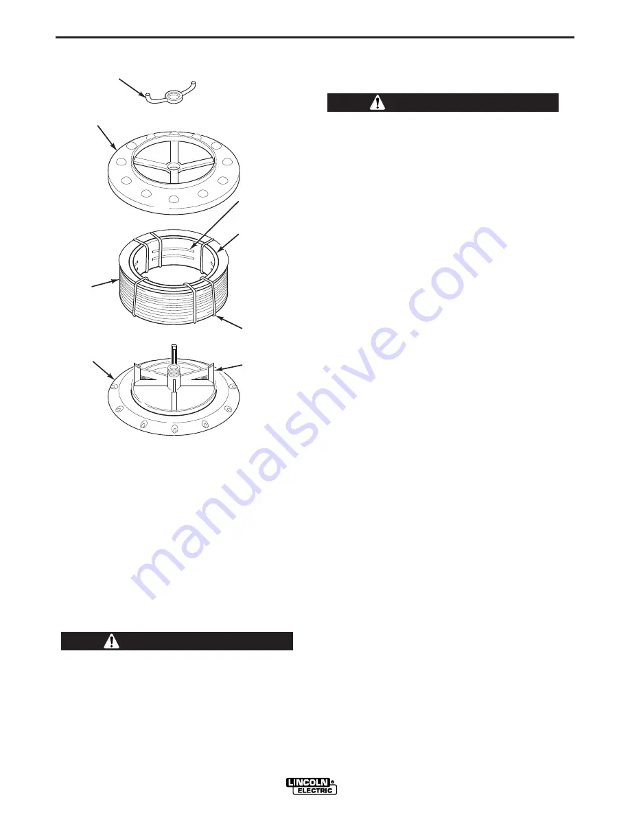
FIGURE B.1 – LOADING A 50 OR 60 LB COIL.

SPINNER

NUT

COVER

PLATE

COIL

REEL

SLOTS

CARDBOARD
COIL
LINER

TIE  WIRE

SPRING
LOADED
ARM

LOADING WIRE DRIVE

a. Turn the reel or spool until the free end of the

electrode is accessible.

b. While tightly holding the electrode, cut off the bent

end and straighten the first six inches. Cut off the
first inch. (If the electrode is not properly
straightened, it may not feed or may not go into
the outgoing guide tube causing a “birdnest”.)

c. Insert the free end through the incoming guide

tube to the drive roll.

d. Turn on the welding power source.

The electrode circuit is electrically 

hot

 when the

power source is on.

------------------------------------------------------------------

WARNING

WARNING

Содержание IM812-A

Страница 1: ... part DO NOT INSTALL OPERATE OR REPAIR THIS EQUIPMENT WITHOUT READING THIS MANUAL AND THE SAFETY PRECAUTIONS CONTAINED THROUGHOUT And most importantly think before you act and be careful For use with machines having Code Numbers 11029 11250 Sales and Service through Subsidiaries and Distributors Worldwide Cleveland Ohio 44117 1199 U S A TEL 216 481 8100 FAX 216 486 1751 WEB SITE www lincolnelectri...

Страница 2: ...R WEARERS SHOULD CONSULT WITH THEIR DOCTOR BEFORE OPERATING Read and understand the following safety highlights For additional safety information it is strongly recommended that you purchase a copy of Safety in Welding Cutting ANSI Standard Z49 1 from the American Welding Society P O Box 351040 Miami Florida 33135 or CSA Standard W117 2 1974 A Free copy of Arc Welding Safety booklet E205 is availa...

Страница 3: ...ical earth ground 3 f Maintain the electrode holder work clamp welding cable and welding machine in good safe operating condition Replace damaged insulation 3 g Never dip the electrode in water for cooling 3 h Never simultaneously touch electrically hot parts of electrode holders connected to two welders because voltage between the two can be the total of the open circuit voltage of both welders 3...

Страница 4: ...event the welding sparks from starting a fire Remember that welding sparks and hot materials from welding can easily go through small cracks and openings to adjacent areas Avoid welding near hydraulic lines Have a fire extinguisher readily available 6 b Where compressed gases are to be used at the job site special precautions should be used to prevent hazardous situations Refer to Safety in Weldin...

Страница 5: ...propriés et non inflammables 4 Des gouttes de laitier en fusion sont émises de l arc de soudage Se protéger avec des vêtements de protection libres de l huile tels que les gants en cuir chemise épaisse pan talons sans revers et chaussures montantes 5 Toujours porter des lunettes de sécurité dans la zone de soudage Utiliser des lunettes avec écrans lateraux dans les zones où l on pique le laitier 6...

Страница 6: ...tion below for future reference This information can be found on your machine nameplate Product _________________________________________________________________________________ Model Number ___________________________________________________________________________ Code Number or Date Code_________________________________________________________________ Serial Number______________________________...

Страница 7: ...ing B 3 Presetting Wire Feed Speed B 4 Making a Weld B 5 Procedure at End of Coil B 6 Open Arc Welding with a Constant Current B 6 Automatic Protection Shutdown B 7 _______________________________________________________________________________________ MAINTENANCE SECTION D Safety Precautions D 1 Routine Maintenance D 1 Circuit Protection and Automatic Shutdown D 1 Adjusting Speed Sensor Module D ...

Страница 8: ...t CC RATED CURRENT Rated current 500 Amps 60 Duty Cycle WIRE SPEED RANGE 50 500 Inches Per Minute IPM 1270 12700 mm Min RECOMMENDED ELECTRODE WIRE SIZES 7 64 Inches 2 78 mm CORED WIRE PHYSICAL DIMENSIONS HEIGHT WIDTH DEPTH WEIGHT 27 Inches 14 25 Inches 33 Inches 82 lbs 686 mm 362 mm 838 mm 37 kg RATED C CURRENT WIRE F FEED S SPEED PHYSICAL DIMENSIONS WIRE D DIAMETER VOLTAGE TECHNICAL SPECIFICATION...

Страница 9: ... 2 to 4 on the power source terminal strip so the output will be energized when the power source is turned on NOTE DC 400 machines above Code 9200 have an output toggle switch to perform this function b Connect the electrode cable to the output terminal of polarity required by electrode Connect work lead to other output terminal SAFETY PRECAUTIONS The electrode circuit including welding wire wire ...

Страница 10: ...ceptacle on the front panel of the wire feeder case c Place Set to Same Polarity As Electrode Cable Connection switch at appropriate position d Place power source toggle switch in Output Control at DC CV 400 position unless a remote control is connected to 75 76 and 77 on the power source terminal strip e If power source has a mode switch set switch to Constant Voltage Innershield Initially set th...

Страница 11: ...move the drive roll from the shaft 3 The new roll to be installed is stamped for the size to be fed An A after the size indicates aluminum wire Remove the rolls from the kit and wipe them clean Wipe the output shaft and locating shoulder clean 4 Use the drive key clamping collar and hex head screw to install the roll on the output shaft Certain size drive rolls consist of two roll halves and may c...

Страница 12: ...e voltage power sources Wire speed is presettable on a calibrated dial The power sources recommended for use with the LN 35 include the DC 250 400 600 CV 400 and R3S type transformer machines and the SAM 400 650 engine welders as well as the SA 200 250 or SAE 300 400 with CV Adapter WELDING CAPABILITY The LN 35 will handle up to 500 Amp 60 duty cycle welding currents LN 35 INSTRUMENTS AND CONTROLS...

Страница 13: ...d remove the remaining tie wires 9 Replace the reel on the wire feeder WORK CLIP LEAD IMPORTANT SAFETY NOTE To avoid possible electrical shock do not touch the metal portions of the LN 35 work lead clamp if the power source output is on The clamp will be electrically HOT to work if the input electrode cable to the LN 35 is electrically HOT even if the gun trigger is off Care should be taken to onl...

Страница 14: ...hut off the power source then loosen the gun cable clamping screw in the gearbox conductor block and pull the gun cable forward about six inches There should be a slight waviness in the exposed wire If there is no waviness the pressure is too low Increase the pressure setting 1 4 turn lock the gun cable in place and repeat the above steps LN 35 FIGURE B 1 LOADING A 50 OR 60 LB COIL SPINNER NUT COV...

Страница 15: ...e level The LN 35 permits accurate VV CC mode presetting of the desired wire feed speed for the desired arc voltage to be used by setting the Wire Speed dial in the following manner before welding a Set Wire Feed Mode switch to VV CC position FIGURE B 3 CC WIRE SPEED SETTING b Referring to the graph shown in Figure B 3 1 Select the horizontal line representing the DE SIRED IN MIN for the welding p...

Страница 16: ...35 Arc Volts Used Desired In Min 16 18 20 22 24 26 28 30 32 34 50 109 97 88 80 73 67 63 58 55 51 60 131 117 105 95 88 81 75 70 66 62 70 153 136 123 111 102 94 88 82 77 72 80 175 156 140 127 117 108 100 93 88 82 90 197 175 158 143 131 121 113 105 98 93 100 219 194 175 159 146 135 125 117 109 103 110 241 214 193 175 160 148 138 128 120 113 120 263 233 210 191 175 162 150 140 131 124 130 284 253 228 ...

Страница 17: ...g Load a new coil of wire and feed it through the cable as described in Loading Electrode Section OPEN ARC WELDING WITH A CONSTANT CURRENT formerly variable voltage POWER SOURCE Although a constant voltage CV power source is recommended for Innershield and gas metal arc welding GMAW satisfactory general purpose welding may be obtained using the LN 35 with a constant current CC power source for non...

Страница 18: ...sing a CC power source and requires a more refined operator technique than when using a CV power source Improved performance can be obtained on CC power source applications within the following guidelines 1 Flatter slope power sources with higher arc force short circuit current will improve performance over steep slope machines The steeper the slope the more critical it is to hold proper electrode...

Страница 19: ...be changed The drive rolls for 035 through 052 cored electrode and 1 16 through 5 64 electrode have a double set of teeth so they can be reversed for additional life Drive rolls for 023 through 052 solid electrode and aluminum sizes have no teeth but use two grooves so they also can be reversed for additional life See Wire Feed Drive Roll and Guide Tube Kits Sec tion for roll changing instructions...

Страница 20: ...eed dial is achieved by proper mounting of the dial knob to the speed potentiometer shaft Whenever the knob is removed the dial is recalibrated as follows NOTE Knob set screw does not seat on shaft flat 1 Be sure the Wire Speed potentiometer mounting nut is securely tightened then rotate the potentiometer shaft so its flat faces about to the 100 mark on the calibrated dial 2 Set WIRE FEED MODE swi...

Страница 21: ...CAUSE lists the obvious external possibilities that may contribute to the machine symptom Step 3 RECOMMENDED COURSE OF ACTION This column provides a course of action for the Possible Cause generally it states to contact your local Lincoln Authorized Field Service Facility If you do not understand or are unable to perform the Recommended Course of Action safely contact your local Lincoln Authorized...

Страница 22: ...mper plug on control or option board may be loose or missing 5 The power source O C V must be above 15 VDC But not more than 110 VDC 6 The gun trigger may be faulty Replace gun 1 The drive motor may be overloaded Check the wire feeding system EX Drive roll tension reel brake and gun cable liner 1 If the power source is a constant current type supply the arc voltage may be dipping below 15 VDC caus...

Страница 23: ...trode stubbing into plate when welding Motor feeds but there is no wire feed speed control 1 Worn and or melted contact tip Replace 2 Worn work cable or poor work connection 3 Loose electrode connect ions Check for loose or faulty connections 4 Wrong electrode polarity for process being used 1 Contaminated weld joint or improper procedures Clean joint and check procedure wire speed and all voltage...

Страница 24: ... LN 35 N F THE 67 LEAD TO THE POLARITY SWITCH COMES FROM THE CONDUCTOR BLOCK AND THE INPUT CABLE CONNECTS DIRECTLY TO THE CONDUCTOR BLOCK N A N B BOTH JUMPER PLUGS MUST BE USED CONNECTIONS AS VIEWED FROM BACK OF RHEOSTAT AND SWITCHES NOTES U B R 500 555 512 J4 CONNECTOR CAVITY NUMBER INPUT CABLE LEGEND S1 POLARITY SWITCH S3 WIRE FEED MODE SWITCH L12032 CR35795 1 06 05 N B N B N B N F N N A A 7 8 9...

Страница 25: ...NOTES LN 35 ...

Страница 26: ...electrically live parts or electrode with skin or wet clothing Insulate yourself from work and ground No toque las partes o los electrodos bajo carga con la piel o ropa moja da Aislese del trabajo y de la tierra Ne laissez ni la peau ni des vête ments mouillés entrer en contact avec des pièces sous tension Isolez vous du travail et de la terre Berühren Sie keine stromführenden Teile oder Elektrode...

Страница 27: ... gute Be und Entlüftung des Arbeitsplatzes Mantenha seu rosto da fumaça Use ventilação e exhaustão para remover fumo da zona respiratória Turn power off before servicing Desconectar el cable de ali mentación de poder de la máquina antes de iniciar cualquier servicio Débranchez le courant avant l entretien Strom vor Wartungsarbeiten abschalten Netzstrom völlig öff nen Maschine anhalten Não opere co...

Страница 28: ...s and Service through Subsidiaries and Distributors Worldwide Cleveland Ohio 44117 1199 U S A TEL 216 481 8100 FAX 216 486 1751 WEB SITE www lincolnelectric com World s Leader in Welding and Cutting Products ...

Отзывы: