


A-2
INSTALLATION
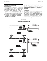
FLEXTEC
®
650x
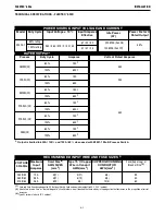
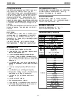
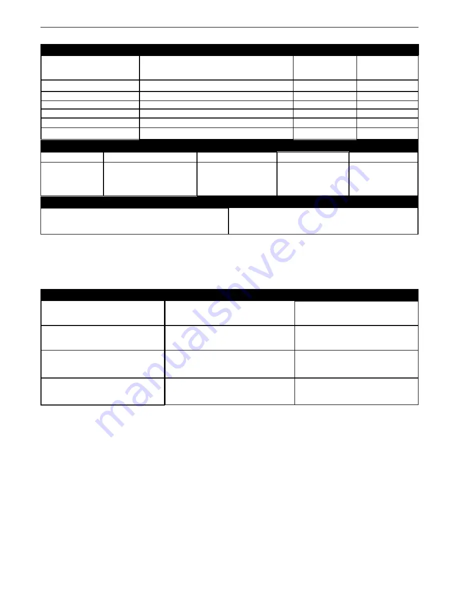
PHYSICAL DIMENSIONS
TEMPERATURE RANGES
HEIGHT
21.8 in (554 mm)
MODEL
K3425-1
WIDTH
16.14 in (410 mm)
DEPTH
29.33 in (745 mm)
WEIGHT
165lbs (74.8kg)
*
OPERATING TEMPERATURE RANGE
Environmentally Hardened: 14°F to 131°F (-10°C to 55°C
**
)
STORAGE TEMPERATURE RANGE
Environmentally Hardened: -40°F to 185°F (-40°C to 85°C)
PROCESS
GMAW (CV)
GTAW (CC)
SMAW (CC)
FCAW-G (CV)
FCAW-S (CV)
SAW (CV)
OUTPUT RANGE (AMPERES)
40-815
10-815
15-815
40-815
40-815
40-815
OCV (U
o
)
60
24
60
60
60
60
OCV (U
r
)
---
15
15
---
---
---
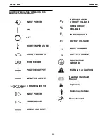
WELDING PROCESS
IP23 180º(H) Insulation Class
*
Weight does not include input cord.
**
Power Source is de-rated at temperatures above 40C.
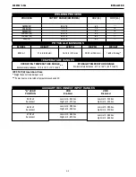
"A" LEAD
POSITION
380 Volt
Reconnect
460 Volt
Reconnect
575 Volt
Reconnect
VRD
Enabled
Low Limit - 340 Vac
High Limit - 420 Vac
Low Limit - 390 Vac
High Limit - 505 Vac
Low Limit - 485 Vac
High Limit - 620 Vac
VRD
Disabled
Low Limit - 340 Vac
High Limit - 455 Vac
Low Limit - 390 Vac
High Limit - 520 Vac
Low Limit - 485 Vac
High Limit - 655 Vac
AUXILIARY RECONNECT INPUT RANGES
Содержание Flextec 650x
Страница 37: ...F 2 DIAGRAMS FLEXTEC 650x L16096 2 A 01 15 97 15 09 26 85 29 31 21 16 21 83 23 66...
Страница 38: ...Flextec 650x 12596...
Страница 43: ...P 1101 C jpg Case Front Assembly Flextec 650x 12596 5 Printed 01 03 2017 at 13 39 33 Produced by Enigma...
Страница 46: ...P 1101 D jpg Divider Panel Assembly 8 Flextec 650x 12596 Printed 01 03 2017 at 13 39 33 Produced by Enigma...
Страница 49: ...P 1101 E jpg Base Assembly Flextec 650x 12596 11 Printed 01 03 2017 at 13 39 33 Produced by Enigma...
Страница 51: ...P 1101 F jpg Case Back Assembly Flextec 650x 12596 13 Printed 01 03 2017 at 13 39 33 Produced by Enigma...
Страница 53: ...P 1101 G jpg Covers Assembly Flextec 650x 12596 15 Printed 01 03 2017 at 13 39 33 Produced by Enigma...