


FineLine 300HD Plasma System
BK8053-000107 Rev A.01
This information is subject to the controls of the Export Administration Regulations [EAR]. This information shall not be provided to
non-U.S. persons or transferred by any means to any location outside the United States contrary to the requirements of the EAR.
Page 42 of 118
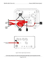
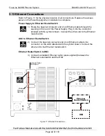
3.13 Ethernet Connections
Refer to Figure 11 for the physical location of all connections. Replace the access
panel on the Power Supply when installation is complete.
Power Supply to Ethernet Router/Switch
1) Route the bayonet connector end of an Ethernet cable through the
opening in the rear of the Power Supply. Plug it into the connector
labelled with the symbol shown. Connect the other end to the Ethernet
router/switch.
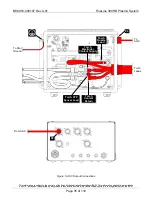
AGC to Ethernet Router/Switch
2) Connect the bayonet connector end of an Ethernet cable to the
connector on the AGC labelled with the symbol shown. Connect the
other end to the Ethernet router/switch.
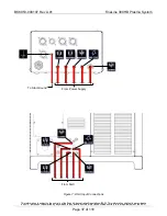
Ethernet Router/Switch to HMI
3) Connect a standard Ethernet cable (user-supplied) between the
Ethernet router/switch and the HMI.
Figure 11: Ethernet Connections
Access Panel
Removed
Ethernet
Router/Switch
HMI
Route
through
opening