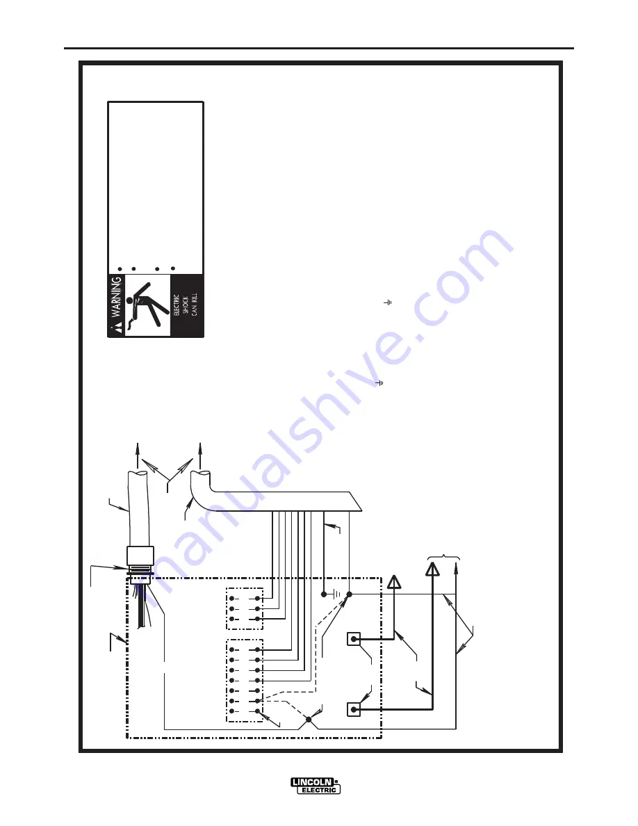
Lincoln Electric DC-655 IM602-A Скачать руководство пользователя страница 39

F-3

DIAGRAMS

F-3

DC-655


A

bove diagram shows electrode connected positive

.


T

o change polarity

,

 turn power off

,

 reverse the electrode and work leads at the power

NEGATIVE

POSITIVE

32 31 2 4

GND

21

N.A.

N.D.

ELECTRODE


CABLE

TO


WORK

POWER


SOURCE

O

nly qualified persons should install

,

 use or

service this machine

.

D

o not operate with covers removed

.

D

isconnect power source before

servicing

.

D

o not touch electrically live parts

.


CONTROL


BOX

21

FOR


CONTROL


CABLE

WITH


14


PIN

MS-TYPE

PLUG


CONNECTOR

OR

FOR


CONTROL


CABLE

WITH


TERMINAL


STRIP

LEAD


CONNECTORS


CONTROL


CABLE


S22

97

8


N.B.


&


N.C.

14-PIN

RECEPTACLE

7

5

7

6

77

        remote voltage sensing work lead may be ordered for this purpose

.


I

f lead #

21

 is to be connected to

the terminal strip

,

 connect to the #

21

 terminal that matches

work polarity

.


T

his

 connection must be changed whenever the

 electrode polarity is 

changed

.


N.A.


W

elding cables must be of proper capacity for the current and

        duty cycle of immediate and future applications

.


C

onnect it directly to the work piece keeping it electrically

        separate form the welding work lead circuit and connection

.


F

or

        convenience

,

 this extended #

21

 lead should be taped to the

        welding work lead

.

  (

I

f the length of work lead circuit is

        short

,

 and connections can be expected to be reliable

,

 then

        control cable lead #

21

 does not need to be extended and can be

        directly connected to terminal #

21

 on the terminal strip

.


N

ote

        that this is not the preferred connection because it adds error


N.D.


C

onnect the control cable ground lead to the frame terminal

        marked    near the power source terminal strip

.


T

he power

        source grounding terminal (marked    and located near the power

        source input power connections) must be properly connected to

        electrical ground per the power source operating manual

.

        to the wire feeder voltmeter reading

.

)


N.F.

source

.

R

everse the leads on the back of the ammeter and voltmeter

in the automatic control box

.A

lso refer to note 

N.F.

TO


AUTOMATIC

E

Q

UIPMENT

TO


AUTOMATIC


CONTROL


CABLE

        physically suitable for the installation

.


A

S16586-

[

LENGTH

41

423

1

32

7

5

7

6

77

N.F.

21

-

21

+

REMOTE


VOLTAGE


SENSING


LEAD


N.C.


T

ape up bolted connection if lead #

21

 is extended

.


N.E.


I

f a variable voltage board is present in the automatic controls

,

the jumper lead on the 

VV

 board must be connected to pin "

L

" to

permit the inch down button to operate

.


T

his jumper

,

 however

,

 will disable the cold starting/autostop feature of the automatic

controls

,

 permitting only hot starting techniques to be used

.

         or from 

14-

pin receptacle using #

14


AWG

 or larger insulated wire 

N.B.


E

xtend lead #

21

 from control cable with terminal strip connectors

10-30-

9

8F


N.G.


I

llustration does not necessarily represent actual position of

 manual for more information

.

N.G.

         CONNECTION OF NA-3, LT-5 OR LT-7 TO THE CV-655, DC-655 OR DC-600 POWER SOURCE        

 appropriate output studs

.


R

efer to power source operating

F

or proper setting of switches on power source

,

see power source operating manual

.

Содержание DC-655 IM602-A

Страница 1: ...STALL OPERATE OR REPAIR THIS EQUIPMENT WITHOUT READING THIS MANUAL AND THE SAFETY PRECAUTIONS CONTAINED THROUGHOUT And most importantly think before you act and be careful For use with machine Code Nu...

Страница 2: ...WEARERS SHOULD CONSULT WITH THEIR DOCTOR BEFORE OPERATING Read and understand the following safety highlights For additional safety information it is strongly recommended that you purchase a copy of...

Страница 3: ...ooling 3 h Never simultaneously touch electrically hot parts of electrode holders connected to two welders because voltage between the two can be the total of the open circuit voltage of both welders...

Страница 4: ...adjacent areas Avoid welding near hydraulic lines Have a fire extinguisher readily available 6 b Where compressed gases are to be used at the job site special precautions should be used to prevent ha...

Страница 5: ...i s et non inflamma bles 4 Des gouttes de laitier en fusion sont mises de l arc de soudage Se prot ger avec des v tements de protection libres de l huile tels que les gants en cuir chemise paisse pant...

Страница 6: ...ion with the technical assistance of the manufacturer In some cases this remedial action may be as simple as earthing grounding the welding circuit see Note In other cases it could involve constructio...

Страница 7: ...ng Cables The welding cables should be kept as short as possible and should be positioned close together running at or close to floor level Equipotential Bonding Bonding of all metallic components in...

Страница 8: ...important when identifying the correct replacement parts On Line Product Registration Register your machine with Lincoln Electric either via fax or over the Internet For faxing Complete the form on t...

Страница 9: ...ROCESSES AND EQUIPMENT B 1 DESIGN FEATURES AND ADVANTAGES B 1 WELDING CAPABILITY B 2 CONTROLS AND SETTINGS B 3 AUXILIARY POWER B 5 MACHINE PROTECTION B 5 WELDING PERFORMANCE B 6 ______________________...

Страница 10: ...505 10506 10507 10508 10509 10510 100 Duty Cycle 122 61 122 61 49 135 67 5 61 49 122 70 74 56 64 140 70 68 60 Duty Cycle 150 75 150 75 60 166 83 75 60 150 86 90 69 78 172 86 83 Input Current at Rated...

Страница 11: ...1 100 Designates welder complies with International Electrotechnical Commission requirements 974 1 European Models IEC 974 1 Designates welder complies with low voltage directive and with EMC directi...

Страница 12: ...page in this manu al Input power supply entry is through the hole in the Case Back Assembly See Figure A 1 for the location of the machine s input cable entry opening Input Contactor CR1 and reconnect...

Страница 13: ...H2 GND 5 MOUNT THE LINKS IN THE POSITIONS SHOWN CONNECT THE FLEX LEAD AS SHOWN LEADS TO THE INPUT SIDE OF CR1 CONTACTOR AS SHOWN L1 LINES 4 CONNECT TERMINAL MARKED TO GROUND PER LOCAL AND NATIONAL ELE...

Страница 14: ...lower case front Refer to figure A 3 for the location 4 Work Sense lead 21 from the 14 Pin MS recepta cle must be connected to 21 on the terminal strip Note This is how the DC 655 is shipped from the...

Страница 15: ...ian Code 10502 receptacle is a NEMA 5 15R protected by a 15 amp breaker 220VAC RECEPTACLE EUROPEAN AND EXPORT MODELS ONLY A Continental European receptacle is located on the rear panel for supplying 2...

Страница 16: ...ense lead connection points on the terminal strip Connect both the work sense lead 21 from the 14 pin connector and 21 lead of the control cable to 21 when welding positive polarity or to 21 when weld...

Страница 17: ...d for use with Lincoln s DH 10 or LN 10 as well as the LN 7 LN 7 GMA LN 15 LN 742 LN 8 LN 9 LN 9 GMA LN 23P and LN 25 semiautomatic wire feeders It is also recom mended for use with the NA 3 NA 5 and...

Страница 18: ...nd thermostatic protection for current overload and excessive temperatures 42 VAC 10 amp auxiliary power available for the wire feeder circuit breaker protected 115 VAC auxiliary power protected by a...

Страница 19: ...REMOTE position the DC 655 s output terminals will be electrically cold until a remote device such as a wire feeder closes the 2 and 4 circuit in the MS receptacle or terminal strip When this switch...

Страница 20: ...eld current that linearly increases as the welding voltage decreases below a level determined by the setting of the constant current control The Arc Force control knob located behind the latched cover...

Страница 21: ...220VAC auxiliary circuit located in the 220VAC receptacle AUXILIARY POWER 42 volt AC auxiliary power as required for some wire feeders is available through the wire feeder recepta cle A 10 amp circui...

Страница 22: ...ot be present This input shut down is reset by turning the DC 655 input power off then on If the fault is not corrected however the shutdown will re occur when turning on the input power SHORTED RECTI...

Страница 23: ...hind the latched cover adjust Arc Force from Min no current increase to Max about 9A V increase A general guideline for CC welding is to set Arc Force to Mid position 5 and increase typically no more...

Страница 24: ...Dual process switch NOTE A dirty air filter may cause the thermal protec tion of the DC 655 to prematurely activate Remove and blow out or wash and dry the filter every two months or less if in extre...

Страница 25: ...either or both sides of the box and with proper connection can provide polarity change with just a switch change Selecting one side only energizes those output studs and opens the other side Installat...

Страница 26: ...Blow out the welder with low pressure air at regular intervals to eliminate excessive dirt and dust build up on inter nal parts 3 Periodically check the welding cables Inspect for any slits or punctur...

Страница 27: ...AUSE lists the obvious external possibilities that may contribute to the machine symptom Step 3 RECOMMENDED COURSE OF ACTION This column provides a course of action for the Possible Cause generally it...

Страница 28: ...d to the DC 655 machine 2 The power switch SW1 may be faulty 3 The pilot transformer may be faulty If Power Pilot light is on 1 The input contactor may be faulty 2 Input shutdown may be activated LED3...

Страница 29: ...W3 and associated leads See wiring diagram 2 Make sure the remote control leads 75 76 and or 77 are NOT grounded to either welding output 3 Make sure control cable to feeder if used is connected prope...

Страница 30: ...nly No output control in Remote control only 1 Make sure the mode switch is in the proper position for the process 2 Make sure the welding cables are sized correctly and the connec tions are tight 3 M...

Страница 31: ...BLE CAUSE RECOMMENDED COURSE OF ACTION Machine will not weld OCV is less than 1 volt The wire feeder will not come on 1 The machine may be in a over load condition Refer to Machine Protection in the o...

Страница 32: ...BLE CAUSE RECOMMENDED COURSE OF ACTION Poor arc characteristics 115VAC receptacle not working 1 The negative welding cable may be connected to the wrong induc tance tap 2 Make sure the mode switch is...

Страница 33: ...uld prevent the fan from turning 2 Check the fan control circuit See wiring diagram 3 The fan motor may be faulty 4 The Thermal Fan Snubber PC board may be faulty See PC board LED information 1 The Th...

Страница 34: ...be receiving the auxiliary or sensing voltages Check plug P3 and plugs P12 P13 See wiring diagram 2 The current feedback circuit may be faulty From the shunt to the control board See wiring dia gram...

Страница 35: ...indings for a possible open 5 LED s 1 through 6 indicate gate signals are being sent to the main SCR s 1 through 6 respectively If LED5 is on CONTROL BOARD along with LED7 8 and 9 on firing PCB and LE...

Страница 36: ...ld replace PCB 2 LED2 when ON indicates welding current greater than 50 amps If ON and not drawing more than 40 amps replace PCB 3 LED3 when ON indicates Main SCR S need cooling and turns fan ON If ON...

Страница 37: ...adds error to the LN 7 voltmeter Above diagram shows electrode connected positive To change polarity turn power off reverse the electrode and work leads at the power 41 4 2 31 32 75 76 77 NEGATIVE PO...

Страница 38: ...r the electrode polarity is changed N G If lead 21 is to be connected to the terminal strip connect to N F The LN 9 voltage control jumpers must be connected as follows refer to LN 9 Operating Manual...

Страница 39: ...al 21 on the terminal strip Note that this is not the preferred connection because it adds error N D Connect the control cable ground lead to the frame terminal marked near the power source terminal s...

Страница 40: ...t the power source physically suitable for the installation An S16586 LENGTH N D N F INPUT CABLE PLUG CONTROL CABLE 41 4 2 31 32 75 76 77 N F 21 21 REMOTE VOLTAGE SENSING LEAD TO NA 5 5R BOLT TO CABLE...

Страница 41: ...UT CONTROL OUTPUT CONTROL OUTPUT CONTROL TRIGGER CIRCUIT Only qualified persons should install use or service this machine Do not operate with covers removed Disconnect power source before servicing D...

Страница 42: ...M FOR CODES 10501 10503 10504 10505 This diagram is for reference only It may not be accurate for all machines covered by this manual The specific diagram for a particular code is pasted inside the ma...

Страница 43: ...F 7 DC 655 This diagram is for reference only It may not be accurate for all machines covered by this manual The specific diagram for a particular code is pasted inside the machine on one of the encl...

Страница 44: ...F 8 DC 655 This diagram is for reference only It may not be accurate for all machines covered by this manual The specific diagram for a particular code is pasted inside the machine on one of the encl...

Страница 45: ...F 9 DIAGRAMS F 9 DC 655...

Страница 46: ...F 10 DIAGRAMS F 10 DC 655...

Страница 47: ...electrically live parts or electrode with skin or wet clothing Insulate yourself from work and ground No toque las partes o los electrodos bajo carga con la piel o ropa moja da Aislese del trabajo y...

Страница 48: ...e Be und Entl ftung des Arbeitsplatzes Mantenha seu rosto da fuma a Use ventila o e exhaust o para remover fumo da zona respirat ria Turn power off before servicing Desconectar el cable de ali mentaci...

Страница 49: ...and Service through Subsidiaries and Distributors Worldwide Cleveland Ohio 44117 1199 U S A TEL 216 481 8100 FAX 216 486 1751 WEB SITE www lincolnelectric com World s Leader in Welding and Cutting Pr...

Отзывы: