


7
WELDING WITH TIG METHOD
To begin welding process with TIG method you should:
•
Do full installation.
•
Connect the ground welding cable to the work piece
by means of the work clamp. You should ensure a
good electric contact.
•
Connect the welding torch for TIG welding by
connecting welding cable to the “-“ socket.
•
Connect the welding cable with the work clamp to the
“+” socket.
•
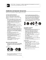
Switch mains power of the rectifier on by setting the
main switch in the position “I” – power supply
indicator should light.
•
Set the proper value of welding current with the knob
of welding current setting depending on he diameter
of the tungsten electrode and thickness of welded
material.
•
Push the button on the welding torch before welding
beginning – it causes activating of the gas valve and
shielding gas preflow.
•
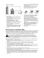
Initiate the welding arc by slight touching of the
ceramic part of the torch to the welded material –
position A on the below drawing.
•
Rotate the torch "from down to up" by inclination of
the wrist and touch the electrode to the welded
material - position B on the drawing.
•
Rotate the torch to the initial position by the
opposite rotary movement of the wrist "from up to
down", and slightly rip off the tungsten electrode from
the welded material - position C on the drawing.
•
The seams are made by shifting the welding torch at
the angel from 70° to 80° with relation to the welded
material.
•
The technique of seam laying down depends on joint
type, material tick-ness and welding position.
•
Welding is finished by pulling the electrode away
from the welded material.
•
Put away the torch on the insulated place after
welding finishing.
Electromagnetic Compatibility (EMC)
11/04
This machine has been designed in accordance with all relative directives and norms. However, it may still generate
electromagnetic disturbances that can affect other systems like telecommunications (telephone, radio, and television) or
other safety systems. These disturbances can cause safety problems in the affected systems. Read and understand
this section to eliminate or reduce the amount of electromagnetic disturbance generated by this machine.
This machine has been designed to operate in an industrial area. To operate in a domestic area it is
necessary to observe particular precautions to eliminate possible electromagnetic disturbances. The
operator must install and operate this equipment as described in this manual. If any electromagnetic
disturbances are detected the operator must put in place corrective actions to eliminate these disturbances
with, if necessary, assistance from Lincoln Electric.
Before installing the machine, the operator must check the work area for any devices that may malfunction because of
electromagnetic disturbances. Consider the following.
•
Input and output cables, control cables, and telephone cables that are in or adjacent to the work area and the
machine.
•
Radio and/or television transmitters and receivers. Computers or computer controlled equipment.
•
Safety and control equipment for industrial processes. Equipment for calibration and measurement.
•
Personal medical devices like pacemakers and hearing aids.
•
Check the electromagnetic immunity for equipment operating in or near the work area. The operator must be sure
that all equipment in the area is compatible. This may require additional protection measures.
•
The dimensions of the work area to consider will depend on the construction of the area and other activities that are
taking place.
Consider the following guidelines to reduce electromagnetic emissions from the machine.
•
Connect the machine to the input supply according to this manual. If disturbances occur if may be necessary to take
additional precautions such as filtering the input supply.
•
The output cables should be kept as short as possible and should be positioned together. If possible connect the
work piece to ground in order to reduce the electromagnetic emissions. The operator must check that connecting
the work piece to ground does not cause problems or unsafe operating conditions for personnel and equipment.
•
Shielding of cables in the work area can reduce electromagnetic emissions. This may be necessary for special
applications.