B-2
OPERATION
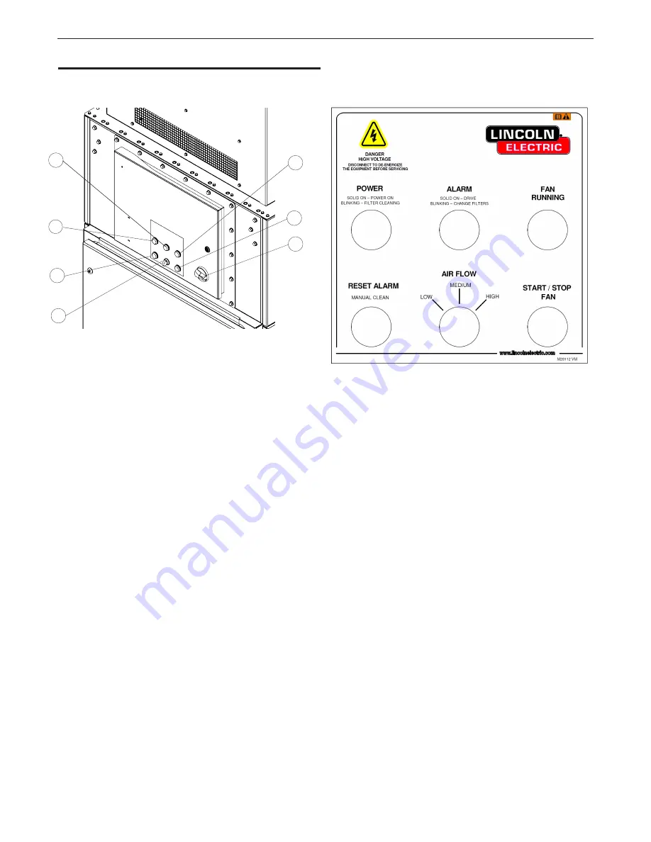
CONTROL
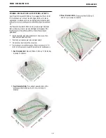
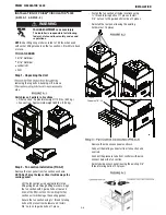
FIGURE B.
2
A.
Power On (Light)
B.
Alarm (Light)
C.
Fan Running (Light)
D.
Reset Drive Alarm (Switch)
E.
Start/Stop fan (Switch)
F.
Main Switch - Input Power
G. Air Flow (Switch)
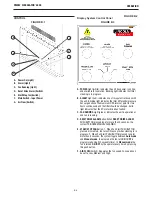
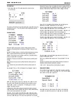
Display System Control Panel
FIGURE B.
3
Functions
A.
POWER
Light (white): indicates the unit has power, is online,
and available for operation. Blinking light indicates that
filter
cleaning is in progress.
B.
ALARM
Light (red): indicates one of two potential issues with
the unit. Blinking light indicates the
filter
differential pressure
has surged above the maximum DP Alarm set point for two
hours continuously and the
filter
should be changed. Solid
light indicates that the
EC motor drive
has
faulted.
C.
FAN RUNNING
Light (green): indicates the unit is operational
and fan is running.
D.
RESET DRIVE ALARM
Button:
When
RESET DRIVE ALARM
PUSH BUTTON pressed long for more than 4 seconds, the
system TRIGGERS MANUAL CLEANING .
E.
START/STOP FAN
Button:
1. When Fan Start PUSH BUTTON
pressed momentary, fan turns ON, except when cleaning is in
progress. 2. When Fan Start PUSH BUTTON pressed long for
more than 4 seconds, the system toggle between
Auto mode
and
Manual mode
. In auto mode the fan turn
ON / OFF
is
programmed using PLCs weekly timer. In
Manual mode
the
fan is turned
ON /OFF
by the operator every time by pressing
this push button.
F.
AIR FLOW
(Switch): Regulates the fan speed. Fan speed can
be set to Low, Medium and High.
A
B
C
E
F
D
PRISM
®
CIRCULATOR 4000
®
G
FIGURE B.
1
Содержание 13232
Страница 39: ...This page intentionally left blank...
Страница 40: ...This page intentionally left blank...
Страница 41: ...This page intentionally left blank...

