B-4
INSTALLATION
APEX
®
30S
Cable Installation
The system is shipped out with cables connected,
how ever the components can be ordered separately
and installed by the end user, or the cables and com-
ponents may be removed during routine maintenance.
For the complete system cable map – see
FIGURES 8
and 9 - System Assembly.
Note:
• Always use the shortest cable lengths possible.
DO NOT coil excess cable. It is recommended that
the total length of control cable does not exceed
100’ (30.5M). The use of non-standard cables in
excess of 25’ (7.5M) can lead to communication
problems (system shut downs), poor motor accelera-
tion (poor arc starting), and low wire driving force
(wire feeding problems).
• Best results will be obtained when the control cables
are routed separate from the weld cables. This mini-
mizes the possibility of interference between the
high currents flowing through the weld cables and
the low level signals in the control cables.:
ArcLink cables can be used to extend the pendant
cable length.
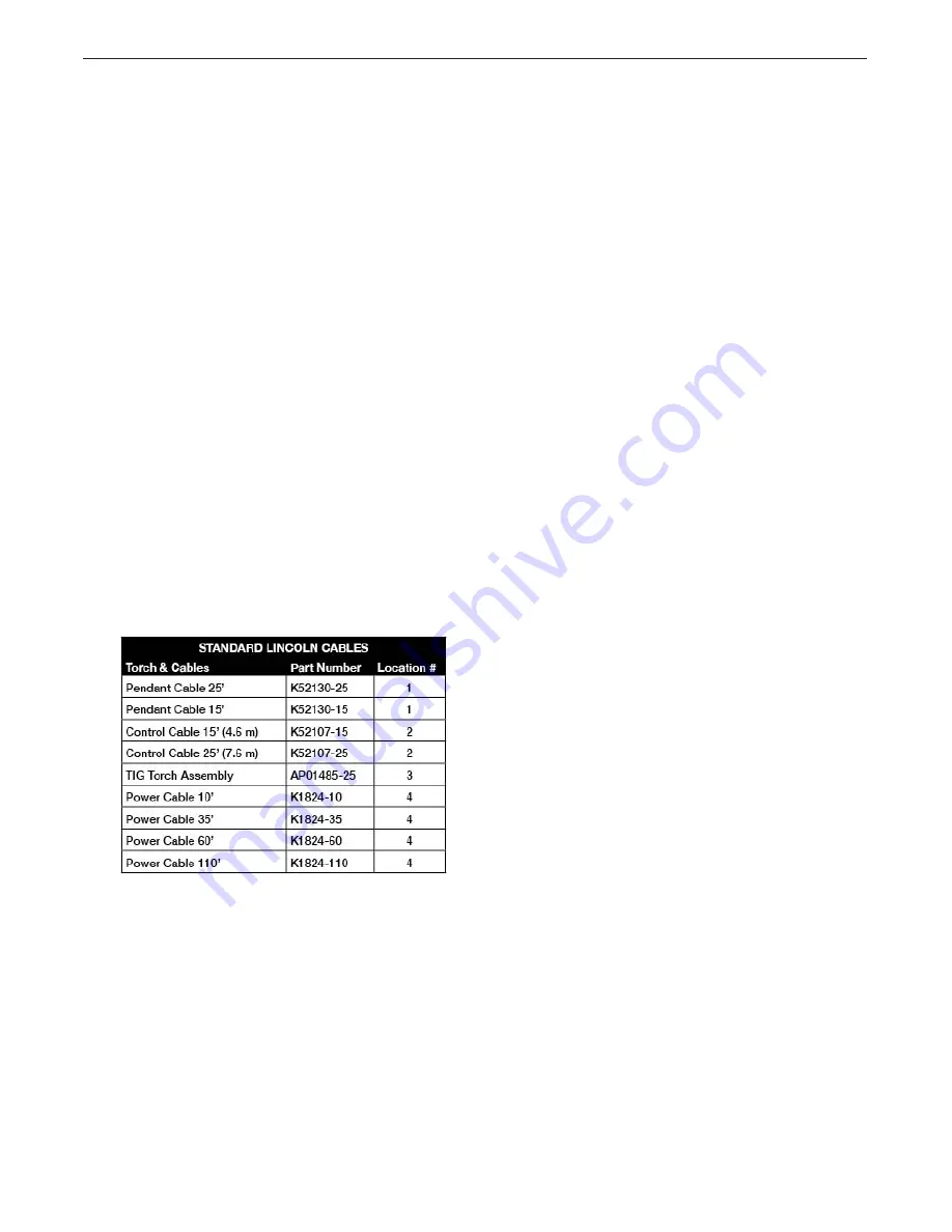
Cable List
1. Pendant Cable -
Connects from the pendant to
the control unit
2. Control Cable -
Connects from the weld head to
the control unit
3. Torch Assembly -
Runs from the control unit
out to the weld head. Includes power, sense lead,
gas and water lines
4. Work Cable* -
Connects from the POWER WAVE
unit (or Advanced Process Module if installed) to
the work piece
5. 3-Phase Power Cable* -
Connects power supply
to facility power (refer to power supply manual for
installation)
6. Gas Hose* -
Supplies gas to the system from
external source
7. Ethernet Cable* -
Optional cable to connect the
power supply to a local area network for added
system functionality
* Indicates items not included with the system


