background image

R356 Controller & Driver 

Page 13 

Version 1.10 

Lin Engineering 


3/16/2018 


7. CONFIGURING AND CONTROLLING THE R356 

 
LinCommand Setup 
For more detailed instructions, please refer to the LinCommand Manual. 


Follow these steps to set up and use LinCommand:   

Note: If LinCommand has not been installed on your computer, you may download the 
program in 32 Bit or, 64 Bit, from one of the links below. After downloading, navigate to the 
‘Setup’ file and double click ‘Setup’ to install. 

LinCommand 32 Bit


LinCommand 64 Bit


1.


After installation, double click on the LinCommand icon 

to launch the LinCommand program. 

2.


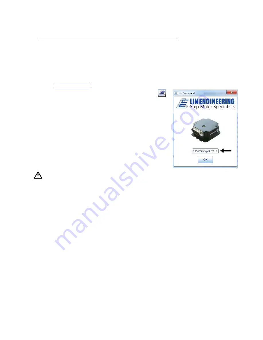
Choose your model controller R256 or, R356 from the drop 
down box and then click [ OK ]. 

3.


LinCommand opens in ‘Normal’ mode with a GUI interface 
for controlling the stepper motor.  For Advance mode skip to 
step 8 below. 

4.


To continue in the ‘Normanl’ mode, choose your COM port, 
baud rate, and controller address (See Figure 9) and then 
click [ Connect ], 

Note: if you are using the USB485 converter card, first download 
driver files for the USB485 

5.


Choose the ‘Motor Settings’ tab.  Set the Run Current*
Hold Current, Step Resolution, Velocity, and Acceleration 
then click [ Add Settings to Queue ].  

CAUTION  Do Not Exceed Motors Peak Current or, 
Damage to the Motor and Controller Could Result!  See “

Setting the Current

” on following page.


6.


Double click on the “Click Here to Add Command” to bring up the motor control menu. 

7.


For a more instructions, please refer to the LinCommand Manual. 

 
8.


To operate in the ‘Advanced mode’, Choose ‘Options’ and select ‘Advanced mode’. 

9.


Select your COM port and baud rated and then click [ Connect ]. 

10.


Enter command strings on one of the 7 lines in the ‘Send’ window and click ‘Send’ to send 
command line to the controller. 

11.


For a complete list of commands and their definitions refer to the R356 Commands manual. 


Example command:  /1A10000R 


This will run unit #1 to the Absolute position 10000 


You can check the address of your driver by checking the dial at the top of the 
driver. (See Figure 9) 


A full list of commands is available in the Silverpak 23C / R356 Command List 


Most common commands to change are: 

o


Step resolution (/1j2R sets R356 to half stepping) 

o


Velocity in pulses/sec (/1V1000R sets the speed to 1000 pps) 

o


Run current (/1m50R sets the run current to 50%) 

o


Hold current (/1h20R sets the hold current to 20%) 

o


Move the motor (/1P800R turns the motor 2 revs if half stepping 1.8°) 


Содержание R356

Страница 1: ...R356 Driver Controller Built in 256x Microstepping Driver and encoder feedback for position correction User Manual Version 1 10 Lin Engineering 16245 Vineyard Blvd Morgan Hill CA 95037 ...

Страница 2: ...ation provided in this document is believed to be reliable However no responsibility is assumed for any possible inaccuracies or omissions Specifications are subject to change without notice Lin Engineering reserves the right to make changes without further notice to any products herein to improve reliability function or design Lin Engineering does not assume any liability arising out of the appli...

Страница 3: ...n page 18 1 02 8 11 09 Added max surface temperature Updated encoder cable image 1 03 9 16 09 Updated image for LED connection 1 04 9 18 09 Updated pinouts and Appendix for step dir mode 1 05 10 29 2009 Added full step as a resolution option 1 06 2 17 2010 Updated typo on page 6 for max step pulse rate 1 07 11 03 2010 Updated step frequency to 16 7MHz 1 08 8 19 2014 Driver outputs updated Replaced...

Страница 4: ...8 Connecting to the USB485 Card 9 Connecting to the RoHS RS232 485 Card 9 6 CONNECTION SPECIFICATIONS Quick Start USB 485 Converter Card 10 Quick Start RS232 485Converter Card 11 Mating Connectors 12 7 CONFIGURING AND CONTROLLING THE R356 LinCommand Setup 13 Setting the Current 14 Connecting Multiple R356 Units 15 Changing the Address of the Controller 16 Connecting Accessories 16 Push Button 16 L...

Страница 5: ... automatically selected upon move completion Designer s Kit with USB communication Here is the list of components if you have purchased the optional Designer s Kit USB to RS485 converter card A switch push button Opto Sensor A USB 6 foot long cable 3 Pin cable optional usage Lin part number USBKIT Designer s Kit with RS232 communication Here is the list of components if you have purchased the opti...

Страница 6: ...gital I O Specifications Number of I O 4 Number of Outputs 2 Input Voltage 0 VDC to 5 VDC 0 to 24V tolerant but 5V recommended Input Current 700 mA Pull up Resistors 20k Ω Protection Static Protection to the microprocessor For a 1 8 stepper Steps per Revolution 200 400 800 1600 3200 6400 12800 25600 51200 Micro step size 1 2 4 8 16 32 64 128 256 3 OPERATING SPECIFICATIONS Maximum Step Frequency 2 ...

Страница 7: ...R356 Controller Driver Page 7 Version 1 10 Lin Engineering 3 16 2018 4 MECHANICAL SPECIFICATIONS Dimensions Figure 1 Dimensions ...

Страница 8: ... FUNCTION I O or Function 1 Green Power Ground 2 Black 1A On Off Output Driver 2 3 White Green Direction Input see Appendix D 4 Yellow 5VDC Input for Opto Isolated STEP and DIR see Appendix D 5 Orange Input 2 Input 2 Jog2 6 Yellow White Internal Power for Opto Sensor 7 Orange White Input 3 Opto Input Input 3 Opto1 8 Black White RS485 A 9 Red 12V TO 40V POWER 10 Blue 1A ON OFF Output Driver 1 11 Bl...

Страница 9: ...ated here Figure 3 USB to RS485 converter card p n USB485 The USB485 converter card does not require power it receives power from the PC Power is still needed for the R356 controller driver Connecting to RS232 card R356 pin R356 color RS232 card pin 4 Black White 1 RS485A 6 Green 2 GND connect to Power Supply Ground 3 Brown 3 RS485B Table 4 Pinouts for using RS232 Figure 4 RS232 to RS485 converter...

Страница 10: ...You may refer to the pin assignments on pages 8 and 9 3 Connect the motor and optional encoder to the R356 4 Your power supply will be connected to the R356 directly The USB485 card is powered via the PC R356 s pin 9 Red wire is 12 to 40VDC pin 1 Green wire is Ground The USB485 converter card s Green wire needs to also connect to the power supply Ground 5 Connect the USB485 card to your PC using t...

Страница 11: ...s 12 to 40VDC pin 1 Green wire is Ground The converter card s green wire needs to also connect to the power supply Ground 2 You may refer to the pin assignments on pages 8 and 9 3 Your power supply will be connected to the RS232 card where the green header is located is for 12 to 40VDC is for the Power Supply Ground 4 Connect the motor and optional encoder to the R356 5 Connect the RS232 card to y...

Страница 12: ...windings The table to the right depicts the function Part 090 00018 Color Function Red A Phase Blue A Phase Green B Phse Black B Phase Table 5 Pin description for Motor Encoder cable This is ideally for a US Digital E2 E5 or E3 encoder One side plugs into the R356 The opposite side has flying leads for connection to encoder Pin Color Function 1 Green Ground 2 White Index 3 Yellow Ch B 4 Red 5VDC 5...

Страница 13: ...urrent Step Resolution Velocity and Acceleration then click Add Settings to Queue CAUTION Do Not Exceed Motors Peak Current or Damage to the Motor and Controller Could Result See Setting the Current on following page 6 Double click on the Click Here to Add Command to bring up the motor control menu 7 For a more instructions please refer to the LinCommand Manual 8 To operate in the Advanced mode Ch...

Страница 14: ...Percent Motor s Current Rating Amps Driver s Equivalent Current Amps 10 0 21 0 30 20 0 43 0 60 30 0 64 0 90 40 0 86 1 20 50 1 07 1 50 60 1 29 1 80 70 1 50 2 10 80 1 71 2 40 90 1 93 2 70 100 2 14 3 00 Table 5 Desired Current To achieve the equivalent Driver Current Amps multiply your motor s rated current by 1 4 Follow these examples Example One You have a motor that is rated at 0 85 Amps 0 85 Amps...

Страница 15: ...our wires power ground RS485 and RS485 prior to plugging into the converter card Figure 7 Connection using RS232 Converter Card If using the USB485 converter card connect all the power and ground lines on the units to the main power supply Then daisy chain the RS485 and RS485 lines prior to plugging into the USB485 card Be sure to also ground the USB485 card with Pin 2 ground Figure 8 Connection u...

Страница 16: ...1P1000R Figure 9 Address Dial Connecting Accessories If you have purchased the Designer s Kit there is a Red Push Button and an Optical Sensor included Follow the schematics below in order to properly assemble accessory pieces Push Button Figure 10 Push Button Schematic Pins 5 7 13 and 14 can all be used with push buttons Below shows the corresponding input numbers for these pins Input 1 Pin 13 In...

Страница 17: ...connection for lighting an LED with 20 mAmps Upon entering command 1J3R both pins 2 10 will output 1 Amps The 1 2k ohm resistor will limit the current to 20 mAmps into the LED Select any ohm value to limit your current based on the device that is connected to the output Optical Sensor Figure 11 Opto Sensor Connection Schematic Use the following table to connect the corresponding wires Optical Sens...

Страница 18: ...ler to zero 3 Issue a 1A100000R and ensure the move completes at a velocity that does not stall 4 Issue a 1 0 to read current position This should be 100000 5 Issue a 1 8 to read the encoder position 6 Issue a 1aE0R which auto divides these two numbers 7 Issue a 1 aE which read backs the encoder ratio computed 8 This value is a rough guide and may be a few counts off due to inaccuracies in the mot...

Страница 19: ...alled moves and will NOT halt any strings or loops upon detection of a stall 3 During position correction mode 1T will halt any move but there is a possibility that the drive may instantly reissue itself a position correction command especially if it is fighting a constant disturbance It may be necessary to issue a 1n0R to positively halt a move in progress 4 Position correction mode is inhibited ...

Страница 20: ...herefore during certain steps Phases A or B will receive 1 4 Amps of current But the average or RMS current throughout these 8 steps is only 1 0 Amps RMS and Amps Phase is the same meaning The 1 4A along this hypotenuse is also known as the 2 Phase On position since both A and B Phases are On and receive current It is also known as the peak current As we see the waveform that s plotted for the A P...

Страница 21: ...o the signal ground that was just created in Step 4 The unit can still accept commands via RS485 when in step direction mode but move commands via RS485 will override step pulses Appendix D Motor Connections Does not apply to SilverPak motors Step Motors have 4 6 or 8 wires To better understand how to connect your step motor with your R356 Controller follow the Figures below for the corresponding ...

Страница 22: ...e wires are used Figure 19 6 Lead Wire Half Winding Connection 6 Lead Wire Motor Connection Full Winding For a full winding connection use both end wires the center tap is ignored NC No Connection Figure 20 6 Lead Wire Full Winding Connection 8 Lead Wire Motor Connection Parallel Connection Eight wire motors can be connected in two ways Parallel and Series When in parallel the wires are simply con...

Страница 23: ... computer but not the driver Go to Device Manager expand Universal Serial Bus controllers Right Click USB485 Choose Properties Select Driver tab and choose Update Driver Browse to Downloads folder click USB485 and choose Next This should correct any USB485 driver problems Hardware Troubleshooting Carefully re check all instructions for hardware and wiring diagrams Many times problems are related t...

Отзывы: