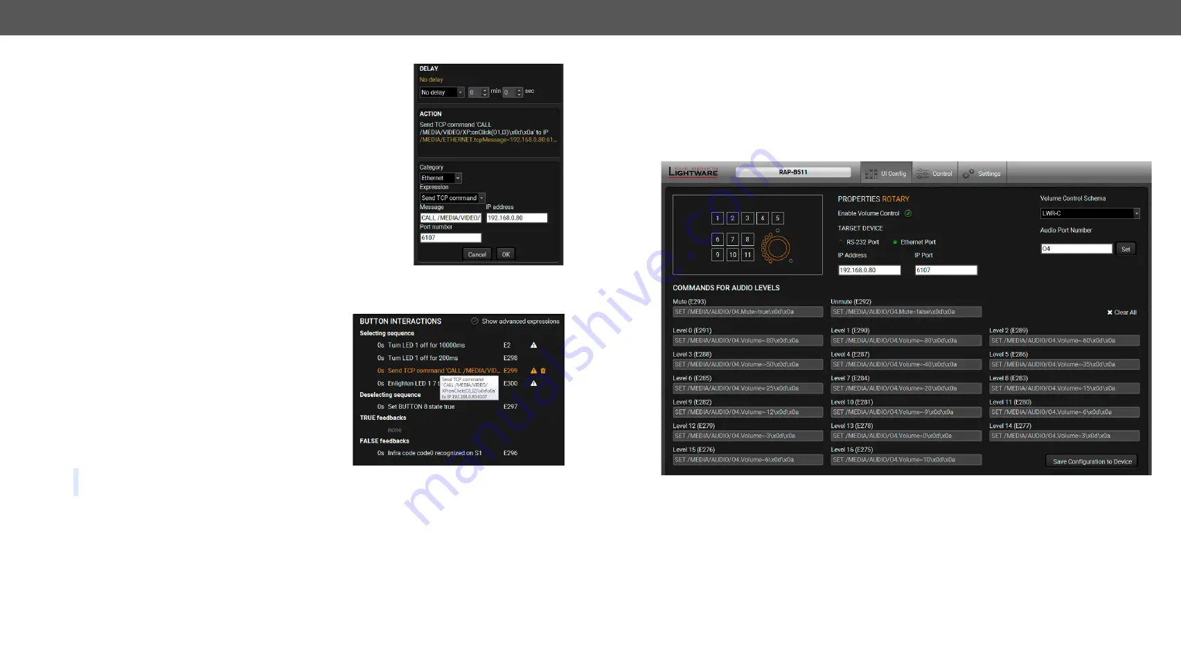
5. Software Control - Lightware Device Controller
RAP-B511 series
– User's Manual
29
Button configuration steps:
Step 1.
Choose the tab and click on the desired action or condition in the
thematic list.
Step 2.
Give the missing parameters (and the delay, if it is necessary) in
the pop up window (on the right).
Step 3.
Click
OK
to save. The configuration is saved as an
Event in
the
It can be seen in the event list, numbered
backwards.
5.4.3.
Button Interactions
This section provides an overview of all defined events
of the selected button. One line represents one event.
It displays the delay time between the action and the
condition, the condition or the action with the parameters,
the event number, where the current setting is saved.
The
icon shows that the event was not created from the
UI config page. It means that an event was set in the
, where the interaction state of the selected button
was defined as an action or condition.
Click on the
icon to
Show advanced expression
. It displays
the LW3 path of the event.
TIPS AND TRICKS: If the Show advanced expression mode is not active, keep the cursor on the event line
for a second, and the whole expression appears in the hint box.
The following settings are available in this section:
▪
The existing events can be edited by clicking on the event line (when it is highlighted with
amber
).
Modifying the event properties is possible in the pop-up window.
▪
Click on the
icon beside the event to delete it.
▪
Clear All
button is for deleting all events of the selected button.
Pop-up window of the action setting
5.4.4. Configurations of the Rotary
Click the rotary icon on wireframe view to display and modify the related configuration.
The jog dial knob can be configured for volume control (or other controlling purposes). Turning left and right
the rotary triggers the command sending via RS-232 or Ethernet.
It is for setting the volume on a 0-16 level scale or the knob press is for toggling between the mute and the
unmute states.
Follow the instructions (below) to set the rotary:
Step 1.
Choose interface for the (volume) command sending (RS-232 port or Ethernet port). When Ethernet
is selected, IP address and port number are also required.
Step 2.
Choose a volume control schema:
LWR
or
Custom
.
a)
LWR
schema is for controlling the volume of the analog audio output levels of the chosen audio port
in any Lightware device. Choose schema in a drop-down menu. (To specify which schema suits your
Lightware device, see the table on the next page). The mute and level entry fields are inactive, because
after giving the audio port number (e.g. I2 or O8), the command schema loaded automatically.
b)
Custom
schema makes possible to send serial or Ethernet messages to the third-party (or Lightware)
device depending on the rotary state. Type the desired commands into the proper entry fields.


