background image

Lightspeed Rocket Hardware Installation Guide

12

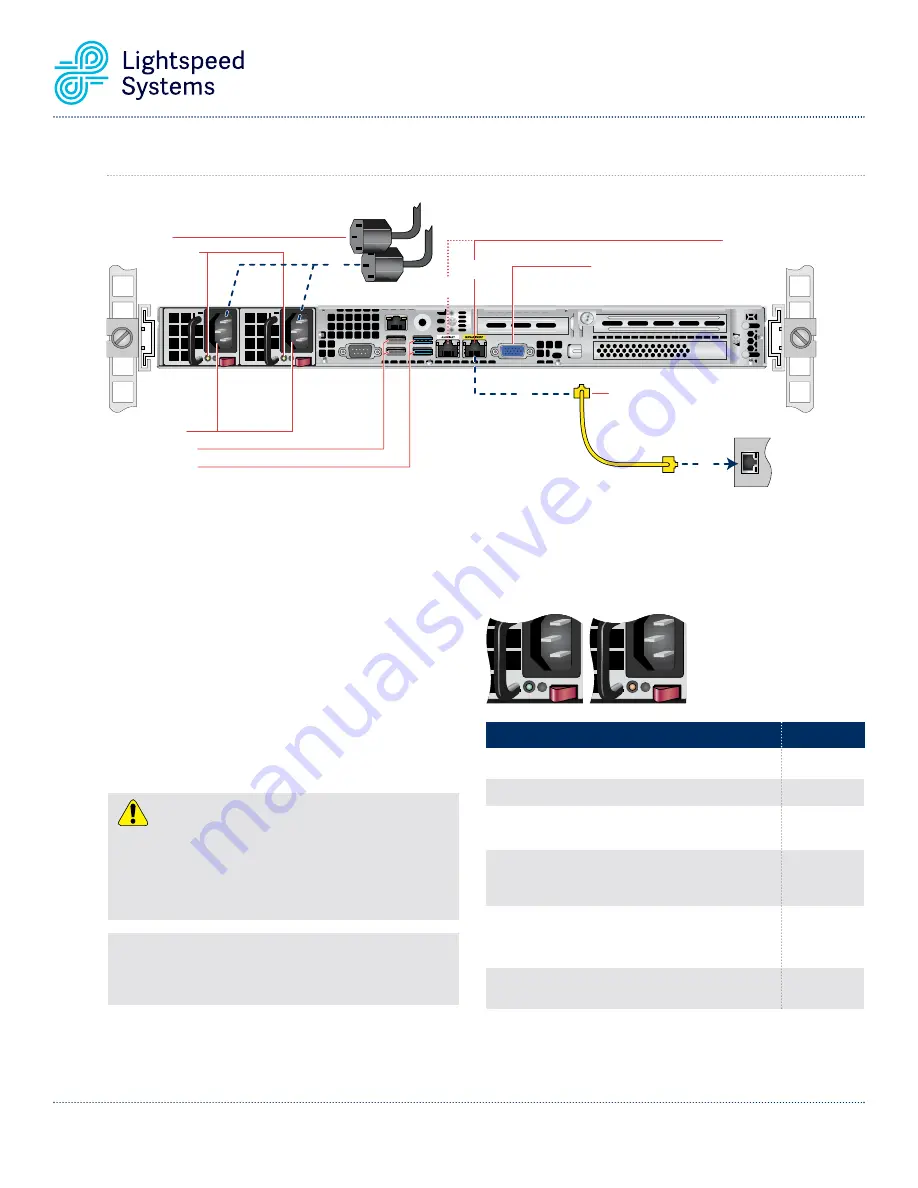
Power Cords

AC Power Inlets
USB Ports (Gen 2)
USB Ports (Gen 3)

Power Good LEDs

4

Ethernet
Cable

Local

Area

Network

2

1

Network Interface
Connectors

Video Port

Management

Port

Auxilliary

Port

ds

Power Corrd
Power Good LEDs

44

Management

Port

Port

xilli

Auxilliary

ideo Port

V

Por

Port

age

Management

Auxilliary

ideo Port

Connectors

Network Interface

USB Ports (Gen 3)

USB Ports (Gen 2)

Inlets

AC Power 

Cable

net

Ether

1

net

Network

ea

Ar

Local

22

10B.

Lightspeed Web Filter Policy Parent Rear Panel Connections

Power Supply Condition 

Output ON and OK

No AC power to both power supplies

AC present / Only 5VSB on (PS off)

AC cord unplugged or AC power lost; with a 
second power supply in parallel still with AC
input power

Power supply warning events where the power
supply continues to operate; high temp, high
power, high current, slow fan 

Power supply critical event causing a shutdown; 
failure, OCP, OVP, fan fail

LED State

GREEN

OFF

AMBER

OFF

1Hz Blinking

AMBER

AMBER

In normal operation the Power Good LED on Power Supply Module
1 and Module 2 will be SOLID GREEN. If the power is down, both
LEDs will BLINK GREEN.

Power Supply Status LED

There is a single bi-color Power Good LED on each
power supply module to indicate power supply status.
The LED operation is defined in the table below.

Step 1

Connect one end of the yellow Ethernet cable 
into the Ethernet port labeled 

MANAGEMENT.

Step 2

Connect the other end of the yellow Ethernet 
cable into an available switch port on your 

Local 

Area Network

. This port will require Internet 

access.

Step 3

Please review the latest Lightspeed Systems 
Rocket Web Filter Product Manual on the 
Lightspeed Systems Community Site at 
(

http://community.lightspeedsystems.com/

documentation/web-filter3/

).

Step 4

Connect the power cords.

Step 5

Proceed to Front Panel Operation on page 17.

NOTE:

The server offers redundant, hot-swap capability. The connections

to AC mains should be made in a manner appropriate to local code and
consistent with customer power distribution with or without redundant
sources.

CAUTION

The power supply is hot-swappable only when you have a server with 
redundant power supplies installed. If you only have one power supply 
installed, before removing or replacing the power supply, you must first
take the server out of service, turn off all peripheral devices connected to
the server, turn off the server by pressing the power button, and unplug the
AC power cord from the server or wall outlet.

Содержание Lightspeed Rocket

Страница 1: ...2500 Bee Cave Road Building 1 Suite 350 Austin TX 78746 Tel 661 716 7600 Toll Free 877 447 6244 www lightspeedsystems com Lightspeed Rocket Hardware Installation Guide...

Страница 2: ...Section 10A Lightspeed Advanced Reporting Bottle Rocket Rear Panel Connections 11 Section 10B Lightspeed Web Filter Policy Parent Rear Panel Connections 12 Section 10C Lightspeed Rocket Web Filter an...

Страница 3: ...A CE Mark Warning This is a Class A product In a domestic environment this product may cause radio interference in which case the user may be required to take adequate measures VCCI Warning This is a...

Страница 4: ...LL RACKS MUST BE MOUNTED SECURELY Ensure that all leveling jacks or stabilizers are properly attached to the rack If installing multiple appliances in a rack make sure the overall loading for each bra...

Страница 5: ...ssembly inside view Adjustable front rack rail assembly attaches to the front of the rack Adjustable rear rack rail assembly attaches to the rear of the rack Eight M5 x 12 Phillips flat head screws Tw...

Страница 6: ...e rack Make sure the rack rail assemblies and screws are aligned in the rack not only in the front and back but are level in height on the left and right sides for proper alignment for appliance insta...

Страница 7: ...Carefully slide the appliance into the rack rails until you hear the locking tabs on the chassis rails click into place Push the appliance all the way into the rack until it stops Secure the unit in...

Страница 8: ...brackets A pair of 2 post rack mounting brackets with threaded holes n A pair of 2 post rack assemblies that attach directly to the rack 2 Post Rack rail assembly outside view 2 Post Rack rail assembl...

Страница 9: ...ning set of short brackets to the long fixed bracket as shown using one M4 truss head screw on each bracket The three holes on the flap will face toward the front for later attachment to the 2 post ra...

Страница 10: ...nce into the rack rails until you hear the locking tabs on the chassis rails click into place Push the appliance all the way into the rack until it stops Secure the unit in the rack by inserting and t...

Страница 11: ...will BLINK GREEN Power Supply Status LED There is a single bi color Power Good LED on each power supply module to indicate power supply status The LED operation is defined in the table below Step 1 Co...

Страница 12: ...BLINK GREEN Power Supply Status LED There is a single bi color Power Good LED on each power supply module to indicate power supply status The LED operation is defined in the table below Step 1 Connec...

Страница 13: ...down both LEDs will BLINK GREEN Power Supply Status LED There is a single bi color Power Good LED on each power supply module to indicate power supply status The LED operation is defined in the table...

Страница 14: ...down both LEDs will BLINK GREEN Power Supply Status LED There is a single bi color Power Good LED on each power supply module to indicate power supply status The LED operation is defined in the table...

Страница 15: ...e latest Lightspeed Systems Rocket Web Filter Product Manual on the Lightspeed Systems Community Site at http community lightspeedsystems com documentation web filter3 Step 4 Connect the power cords S...

Страница 16: ...ply Status LED There is a single bi color Power Good LED on each power supply module to indicate power supply status The LED operation is defined in the table below Step 1 Connect one end of the yello...

Страница 17: ...be SOLID GREEN If the power is down both LEDs will BLINK GREEN Power Supply Status LED There is a single bi color Power Good LED on each power supply module to indicate power supply status The LED op...

Страница 18: ...ed on the far right on the front side of the appliance 3 Once the system has been powered on replace the bezel By powering on the appliance you agree to all terms and conditions included in the End Us...

Отзывы: