

INSTRUCTION SHEET NO.
© 1997
IS:26046
A0197
Page 2 of 2
Power Extention Connector for use with ProSpec
™
Track System Only.
POWER FEED TO THE CONNECTOR(S) (continued)
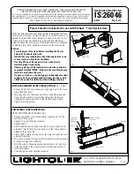
DIRECT POWER FEED FROM A STRUCTURAL SURFACE
--
Fig 4 & Fig. 5
1. Remove the bottom cover (if required) by snapping it out of the
connector. Save cover.
2. Push out hole plug.
3. Thread electrical connector into the end cap.
4. Pass conduit or cable through electrical connector and secure
conduit or cable to electrical connector.
5. Form the wires to the appropriate screw terminals. Cut and strip
wires and attach to the screw terminals. (See wiring section of
instruction sheet).
6. Snap the bottom cover onto the connector.
WIRING THE CONNECTOR--
Fig. 6 & Fig. 7
Note: Multiple circuits can be fed into the Power Extension Connector.
The Connector is not polarized and can be inserted into the track in
any orientation. Therefore identification of the circuits during wiring
needs to be controlled by the installer or electrician. The brass screw
terminals are for the hot leads, the silver screw terminals are for
neutral leads, and terminals marked "GND" are for the ground. The
individual circuits are arranged vertically (see diagrams).
1. Form the wires to the screw terminals, strip the insulation
back 1/2".
2. Slip the wire under the terminal screw head. Tighten all screw
terminals when wiring is completed.
3. Make sure stripped portion of wires are not touching each other.
4. Snap bottom cover onto the connector to cover the wires.
There are additional feed in kits (Floating Canopy, End Feed Canopy,
Floating Invisible Feed, Grid Ceiling Canopy Kit, Stem Kits....) that can
be used with these connectors. See the Instruction Sheet supplied
with the Feed-in Kit for detailed instructions on mounting the kit to the
connector.
Bottom Cover
Track Unit
Dead End
Fig. 4
Power
Extention
Connector
Hole Plug
Track Unit
Conduit or Cable
(by Others)
.50
Ground Terminal
Power
Terminals
Neutral
Terminals
Two wires may be
attached to one
screw terminal.
Circuit 1
Circuit 2
Circuit 2
N
Circuit 1
N
Use 12 ga. solid copper wire for
feed connections including
ground.
Fig. 6
Fig. 5
Fig. 5
Power
Feed
Po
wer
Out
Plain Track
Feed Track
or Power Extension
Connector
Power
Extension
Connector
Power
Feed
Power
Feed
Po
wer
Out
Feed Track
Feed Track
or Power Extension
Connector
Mini Coupler or
In-Line Connector
Feed Track
Power
Feed
Power
Feed
Po
wer
Out
Feed Track
Feed Track
or Power Extension
Connector
Power
Extension
Connector
Power
Extension
Connector
Power
Feed
Structural
Impediment
Fig. 7
Power Extension
Connector
Electrical
Connector
(by Others)
End Cap
Power
Extention
Connector