10
NOTE:
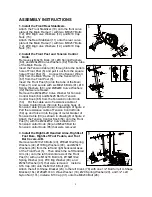
1/2” Bolt for left U-Shape Bracket (16L) and 1/2” Bolt for right U-Shape Bracket (16R)
are marked with “
L
” and “
R
”.
Attach the Left Foot Pedal (36) onto the Left Foot Bar (2L) with three M6x40 Bolts (29), Ø6
Washers (28), and M6 Nylon Nuts (27).
Attach the Foot Bar Covers-A/B (33L, 33R) onto the Left Foot Bar (2L) with two ST4.2x25
Phillips Self Tapping Screws (66).
Repeat above step to attach the Right Handrail Arm (3R) onto the right horizontal axis of the
Front Post (5) and right U-Shape Bracket (23) to the right Crank (78).
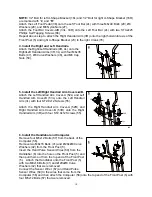
4. Install the Right and Left Handrails.
Attach the
Right/Left Handrails (4R, 4L) onto the
Right/Left Handrail Arms (3R, 3L) with four M6x35
Bolts (47), Ø6 Curve Washers (48), and M6 Cap
Nuts (50).
5. Install the Left/Right Handrail Arm Covers-A/B.
Attach the Left Handrail Arm Cover-A (52L) and Left
Handrail Arm Cover-B (53L) onto the Left Handrail
Arm (3L) with four ST2.9x12 Screws (55).
Attach the Right Handrail Arm Cover-A (52R) and
Right Handrail Arm Cover-B (53R) onto the Right
Handrail Arm (3R) with four ST2.9x12 Screws (55).
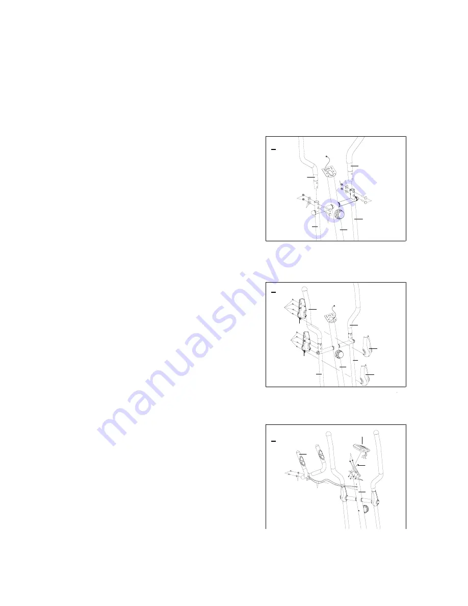
6. Install the Handlebar and Computer.
Remove four M5x12 Bolts (57) from the back of the
Computer (56).
Remove two M8x16 Bolts (41) and Ø20xØ8 Curve
Washers (42) from the Front Post (5).
Insert the Hand Pulse Sensor Wires (69) from the
Handlebar (6) into the hole on the Front Post (5) and
then pull them out from the top end of the Front Post
(5). Attach the Handlebar onto the Front Post (5)
with two M8x16 Bolts (41) and Ø20xØ8 Curve
Washers (42) that were removed.
Connect the Sensor Wire I (67) and Hand Pulse
Sensor Wires (69) to the wires that come from the
Computer (56) and then attach the Computer (56) onto the top end of the Front Post (5) with
four M5x12 Bolts (57) that were removed.
4R
3R
5
3L
4L
50
48
52L
53L
55
55
3L
5
4L
47
52R
4R
3R
47
48
50
53R
5
56
67
57
69
42
41
6
69
4
5
6

