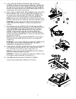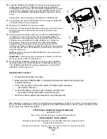
10.
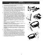
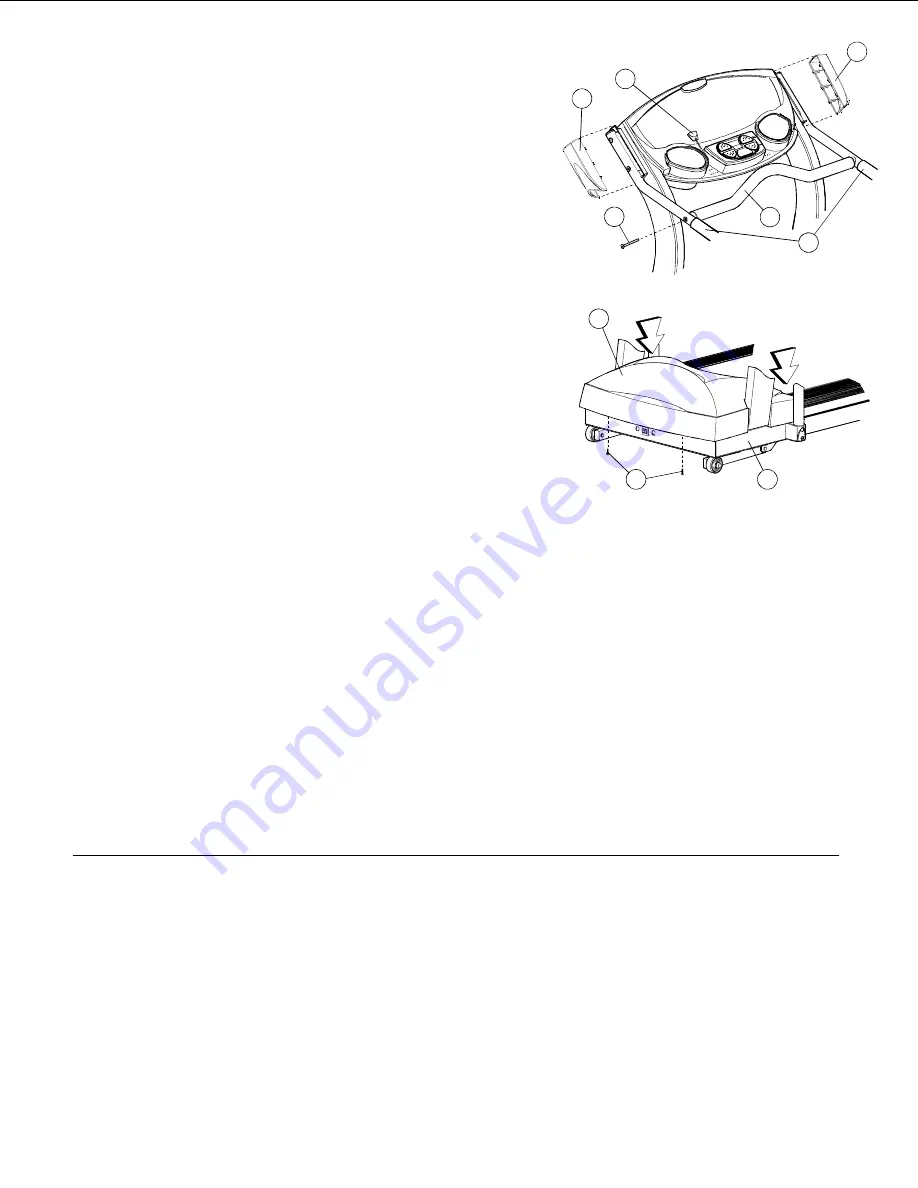
Locate the HANDRAIL CROSSBAR (#9). With the bend facing upward and
pitched toward the DISPLAY CONSOLE, carefully place the HANDRAIL
CROSSBAR between the user LEFT AND RIGHT HANDRAILS (#4) as shown
and align the mounting holes. Insert one SHORT MOUNTING BOLT (#6) on
either end of the
HANDRAIL CROSSBAR and tighten using a 5/32” hex key
wrench.
Securely tighten all mounting bolts on the USER LEFT HANDRAIL (#4).
11.
Securely tighten the four MOUNTING BOLTS (#10) securing the USER LEFT
and RIGHT UPRIGHTS to the FRAME (B).
12.
Place the STOP CORD (#12) in the proper location.
13.
Position the unit in the desired location and plug the power cord into the front of
the unit and then into a wall outlet (See the operation manual for power
requirements.)
14.
Position the MOTOR COVER (A) back over the MOTOR COMPARTMENT
(H). Bring the unit to an incline position (refer to the Operation Manual for
proper start and incline procedures.) Secure the MOTOR COVER (A) to the
FRAME (B) using the two MOTOR COVER SCREWS (#11). Tighten the
screws securely. Press down on the MOTOR COVER at the positions
indicated to secure the Dual-Lock fasteners located under the MOTOR
COVER to the FRAME. Lift lightly on the MOTOR COVER to confirm a positive
lock. Repeat as necessary until the MOTOR COVER is secure. Lower the unit
back to its original level.
NOTE:
Be careful not to pinch the WIRE HARNESS (C) when replacing the
MOTOR COVER (a).
REMARQUE :
Veiller à ne pas pincer le faisceau de CABLES (C) lors de la
remise en place du CAPOT DU MOTEUR (A).
15.
Place an UPPER HANDRAIL COVER (#13) on the top of each HANDRAIL
(#4). Align the tabs of the UPPER HANDRAIL COVERS with the slots in the
TOP HANDRAIL SPACERS (#5) and apply light pressure until the UPPER
HANDRAIL COVERS snap secure.
PRE-OPERATION CHECKLIST
Ensure that all fasteners are tight.
Make sure the STRIDING BELT is properly tensioned and aligned according to the
Operation Manual.
Check the operation of the STOP switch and tether switch assembly.
(See Operation Manual.)
Confirm the display console is set to English or Metric units.
(See Optional Settings ENG/MET in Operation Manual.)
Read the entire Operation Manual before using the treadmill.
Before attempting to operate your Treadmill, it is imperative that you familiarize yourself with the contents of the Operation Manual.
If your Life Fitness treadmill does not respond as described in the OPERATION MANUAL contact the nearest Life Fitness Service
Center as listed in the OPERATION MANUAL.
Life Fitness Customer Support Services
at (800) 351-3737
Prior to your call, please be sure you have located and noted the
MODEL NUMBER & SERIAL NUMBER.
The Model & Serial number information of your Life Fitness Treadmill is contained in a label
located on the front of the unit.
©
2005 Brunswick Corporation. All rights reserved. Life Fitness is a trademark of Brunswick Corporation.
7995101 Rev A2
12/05
8
6
9
12
4
13
13
A
11
B
Press
Press
Содержание Treadmill T3.5
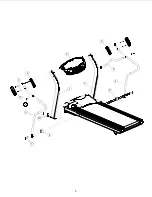
Страница 5: ...5 10 4 6 7 7 5 2 1 3 5 4 9 8 13 8 ...


