background image

7

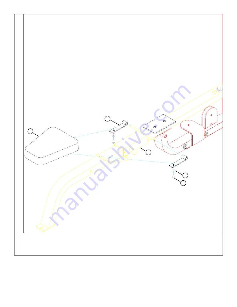
STEP 4:

FIGURE 4

•   Slide two HINGE TABS (46) onto the WOLFF SLEEVE (3) and 

SECURELY

 assemble SEAT PAD (14) using two 3/8 X 1-1/4”

BOLTS (39), and two 3/8” WASHERS (42). See FIGURE  4. 

(NOTE: Please note the HINGE  TAB direction.)

39 3/8 X 1-1/4”

 3

46

14

42

Содержание Strength 8215

Страница 1: ...8215MULTI PRESS Part 6875601 Revision 3 17 00 1 ASSEMBLY INSTRUCTIONS...

Страница 2: ...er 0 1 2 3 4 5 6 1 2 1 2 1 2 1 2 1 2 1 2 BOLT LENGTH There is a risk assumed by individuals who use this type of equipment To minimize risk please follow these rules 2 Do not allow minors or children...

Страница 3: ...27001 DESCRIPTION 1 2 X 6 1 2 BOLT 1 2 X 4 BOLT 1 2 X 3 BOLT 1 2X1 1 4 BOLT 3 8X3 3 4 BOLT 3 8 X 3 1 4 BOLT 3 8 X 3 FLATHEADBOLT 3 8 X 2 3 4 BOLT 3 8 X 2 BOLT 3 8X1 1 4 BOLT 3 8 X 1 BUTTON HEAD 1 2 WA...

Страница 4: ...See FIGURE 1 LOOSELY assemble UPPER SUPPORT 8 to the TOWER 1 and PRESS FRAME 2 using four 1 2 X 3 BOLTS 32 four 1 2 WASHERS 41 and four 1 2 LOCK NUTS 43 See FIGURE 1 SECURELYTIGHTENTHEFRAMECONNECTIONS...

Страница 5: ...SPRINGPINcompletely Attach one U PIN 50 to the WOLFF SLEEVE 3 using one 1 2 PAL NUT 24 Slide one 4 VINYL CAP 25 onto the U PIN 50 as shown in FIGURE 2 Pull back on SPRING PIN andCAREFULLYslide the ass...

Страница 6: ...the PRESS BASE 2 using one 1 2 X 3 BOLT 32 two 1 2 WASHERS 41 and one 1 2 LOCK NUT 43 as well as two 3 8 X 3 FLAT HEAD BOLTS 36 one 1 4 X 8 PLATE 56 two 3 8 WASHERS 42 and two3 8 LOCK NUTS 45 as shown...

Страница 7: ...4 Slide two HINGE TABS 46 onto the WOLFF SLEEVE 3 and SECURELY assemble SEAT PAD 14 using two 3 8 X 1 1 4 BOLTS 39 and two 3 8 WASHERS 42 See FIGURE 4 NOTE PleasenotetheHINGE TABdirection 39 3 8 X 1...

Страница 8: ...PAD ANGLE 10 and the LEFT BACK PAD ANGLE 11 using two 1 2 X 1 1 4 BOLTS 33 two 1 2 WASHERS 41 and two 1 2 LOW HEIGHT LOCK NUTS 44 NOTE Tighten nuts securely then back off 1 4 turn Assemble the 15 1 2...

Страница 9: ...FIGURE 6 9 SECURELY assemble the BACK PAD 13 to the LEFT RIGHT BACK PAD ANGLES 11 10 using four 3 8 X 1 1 4 BOLTS 39 and four 3 8 WASHERS 42 See FIGURE 6 STEP 6 39 3 8 X 1 1 4 13 10 42 11...

Страница 10: ...3 8 WASHERS 42 and four 3 8 LOCK NUTS 45 as shown in FIGURE 7 STEP 7 0 1 2 3 4 5 6 1 2 1 2 1 2 1 2 1 2 1 2 Center PRESS ARM ADJUST 5 on top of the STOP POST on the PRESS BASE 2 and securely tighten s...

Страница 11: ...o the PRESS ARM ADJUST 5 using one 1 2 X 7 1 2 BOLT 29 two 1 2 WASHERS 41 and one 1 2 LOW HEIGHT LOCK NUT 44 NOTE SECURELY tighten then back nut off 1 4 turn to allow the press arm to rotate freely Se...

Страница 12: ...12 0 1 2 3 4 5 6 1 2 1 2 1 2 1 2 1 2 1 2 FIGURE 9 STEP 9 Snap two WEIGHT PLATE BUSHINGS 22 into the top side of all twenty WEIGHT PLATES 16 as shown in FIGURE 9 22 16...

Страница 13: ...with the key hole facing as shown in FIGURE 10 SECURELY assemble the WEIGHT STACK SHAFT 17 to the HEAD PLATE 18 using one 3 8 X 1 1 4 BOLT 39 and one 3 8 WASHER 42 Note The bolt hole in the HEAD PLAT...

Страница 14: ...11 Place TOWER BRACE 7 over the GUIDE RODS 20 and SECURELY assemble TOWER BRACE 7 to the TOWER 1 using two 1 2 X 4 BOLTS 31 two 1 2 WASHERS 41 and two 1 2 LOCK NUTS 43 as shown in FIGURE 12 STEP 12 41...

Страница 15: ...4 1 2 PULLEY 19 to the PRESS BASE 2 usingtwo3 8X3 3 4 BOLTS 34 two3 8 FLANGESPACERS 52 two2 7 8X2 1 4 CABLECLIPS 2 two1 2 SPACERS 53 two 3 8 WASHERS 42 and two 3 8 LOCK NUT 45 as shown in FIGURE 13 NO...

Страница 16: ...9 as shown in FIGURE 14 Wrap the CABLE 21 around one 4 1 2 PULLEY 19 andSECURELYassemblethe4 1 2 PULLEY 19 to the vertical pulley bracket on the PRESS FRAME 2 using two 3 8 X 2 BOLTS 38 andtwo3 8 LOC...

Страница 17: ...emblethe4 1 2 PULLEY 19 tothehorizontalpulleybracket on the PRESS FRAME 2 using one 3 8 X 2 BOLT 38 one 2 7 8 CABLE CLIP 26 and one 3 8 LOCK NUT 45 as shown in FIGURE 15 NOTE Before tightening make su...

Страница 18: ...1 2 PULLEY 19 andSECURELYassemble the 4 1 2 PULLEY 19 to the vertical pulley bracket on the LOWER SUPPORT 6 using two 3 8 X 2 BOLTS 38 and two 3 8 LOCK NUTS 45 as shown in FIGURE 16 NOTE Make sure CA...

Страница 19: ...rm several repetitions on the machine This will relax the cable system and prevent the HEAD PLATE 18 from lifting up If after completing the previous step the HEAD PLATE 18 still does not sit on top o...

Страница 20: ...STEP 18 Slide the SHROUD 15 between the TOWER 1 as shown in FIGURE 18 FIGURE 18 20 0 1 2 3 4 5 6 1 2 1 2 1 2 1 2 1 2 1 2 15 1...

Страница 21: ...ESS If unsure of proper use of equipment call your local LifeFitness distributor or call the LifeFitness customer service department at 800 328 9714 SECURELYassembletheSHROUD 15 totheTOWER 1 usingfour...

Отзывы: