background image

Maintenance

29

4.4

Field Charge Verification

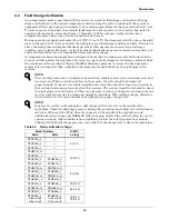
An integral sight glass is provided with the receiver to assist in field charge verification. During 

charge verification set the control temperature down to keep the system running. If the system is 

equipped with hot gas bypass, de-energize it by removing power from the hot gas solenoid valve coil. 

To remove power, disconnect the solenoid leads from the unit contactor in the electric box (refer to 

specific unit schematic; reference Figures 7 through 10). When charge verification has been 

completed, replace and secure all wire connections and covers.
During operation at design ambients (95 or 105°F; 35 or 41°C) the charge level will be above the sight 

glass in the receiver. If levels are below the sight glass an undercharge condition is likely. If levels are 

above the sight glass and higher discharge pressures than normal are observed an overcharge 

condition may be likely. However, verify that other high discharge pressure causes such as dirty coil 

and restricted airflow are not responsible before removing charge.
At temperatures below design ambient, refrigerant backs into the condenser coil and the level in the 

receiver will drop below the sightglass. If you are trying to verify charge level at lower ambients, block 

the condenser coil to maintain 230psig (1585kPa) discharge pressure to ensure the head pressure 

control valve is closed. At these conditions the charge level should be above the sight glass in the 

receiver.

NOTE

The 5-ton high ambient, 5-ton Quiet-Line and 8-ton models consist of two condenser coils and 

two receivers. When restricting airflow on these units, the coils should be blocked off 

proportionally. If one coil is restricted significantly more than the other, liquid can remain in 

the restricted coil causing lower levels in the receivers. The receiver liquid level should be above 

the sight glasses in both receivers. There may be some variation in charge level between the two 

receiver sight glasses due to piping and assembly variations. When adding charge, determine 

which receiver level is lower and use that sight glass to gauge charge level.

NOTE

If no level is visible in the sight glass, add charge until the level is in the middle of the 

sight glass. Check the discharge pressure during this procedure and adjust coil restrictions to 

maintain 230 psig (1585 kPa). Once the charge is in the middle of the sight glass, add 

additional system charge per 

Table 22

. After charging, unblock the coil and allow the unit to 

operate normally. After conditions have stabilized, restrict the coil if required to maintain 

230psig (1585kPa) discharge pressure and verify that the charge level is above the sight glass.

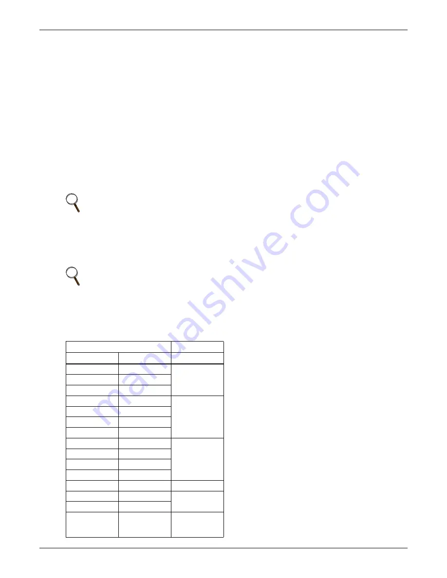
Table 22

Field verification charge

Model Numbers 

R-407C

60Hz

50Hz

oz (kg)

PFH014A-_L

4 (0.11)

PFH020A-_L

PFH027A-_L

PFH027A-_H

18 (0.51)

PFHZ27A-_L

PFH037A-_L

PFH036A-_L

PFH042A-_L

PFH041A-_L

PFH037A-_H

PFH036A-_H

8 (0.23)

PFHZ37A-_L

PFHZ36A-_L

PFH042A-_H

PFH041A-_H

PFHZ42A-_L

PFHZ41A-_L

PFH067A-_L

PFH066A-_L

18 (0.51)

PFH067A-_H

PFH066A-_H

50 (1.42)

PFHZ67A-_L

PFHZ66A-_L

PFH096A-_L

3-ton circuit

5-ton circuit

PFH095A-_L

3-ton circuit

5-ton circuit

18 (0.51)

18 (0.51)

Содержание PFH014A-L

Страница 1: ...Liebert Prop Fan Condensing Unit User Manual 50 60Hz ...

Страница 2: ... BTU Hr P 208 230 1ph 60Hz Y 208 230 3ph 60Hz A 460 3ph 60Hz B 575 3ph 60Hz S 220 1ph 50Hz M 380 415 3ph 50Hz R 407C Refrigerant Standard Coil C Coated Coil PFH 0 37 P L 7 A Air Cooled A L 95 F 35 C Ambient Liebert Lee Temp H 105 F 41 C Ambient Liebert Lee Temp Not all options and or voltage combinations are available Example PFH037A PL7 ...

Страница 3: ...s 16 2 5 3 Field Fabricated Line Sets 16 2 5 4 Installation of Piping to Units 18 2 5 5 R 407C PFH Installed as a Replacement Condensing Unit in an R 22 System 18 2 5 6 General System Charge Requirements 20 2 6 Electrical Connections 21 2 6 1 Low Voltage Control Wire Connections 21 2 6 2 Low Voltage Control Wire Sizing 22 2 7 Electrical Data 22 2 8 Checklist for Completed Installation 24 3 0 OPERA...

Страница 4: ...ble 4 Piping and electrical connections top air discharge 7 Table 5 Pipe length and condenser elevation relative to evaporator 15 Table 6 Equivalent lengths for various pipe fittings ft m 15 Table 7 Refrigerant charge in Liebert pre charged R 407C line sets 16 Table 8 Liebert PFH unit charge levels and coupling size 17 Table 9 Recommended line sizes OD Cu 17 Table 10 Piping connection sizes and to...

Страница 5: ...ontain similar components to the base models except the coils and fans are sized to provide catalog capacity of the appropriate evaporator section up to 105 F 41 C outside ambient temperature 1 1 3 Liebert Quiet Line Models These models contain similar components to the base models except the coils and fans are sized to provide catalog capacity of the appropriate evaporator section up to 95 F 35 C...

Страница 6: ...send a copy of the claim to Emerson Network Power or your local Emerson sales representative If possible maintain equipment and packaging until it is at the installation location 2 2 Location Considerations To ensure an adequate air supply locate all condensing units in a clean air area away from loose dirt and debris that can clog the coil Avoid ground level sites with public access or areas that...

Страница 7: ...18 18 457 351 159 PFHZ37A L PFHZ36A L PFH042A H PFH041A H PFHZ42A L PFHZ41A L PFH067A L PFH066A L Source DPN000130 Rev 1 A B C C Fan Rotation CCW left side Shaded area indicates a minimum clearance of 18 457mm for proper air flow Shaded area indicates a minimum clearance of 18 457mm for proper air flow Shaded area indicates a recommended clearance of 24 610mm for component access and removal DPN00...

Страница 8: ... indicates a minimum clearance of 18 457mm for proper air flow Shaded area indicates a minimum clearance of 18 457mm for proper air flow Shaded area indicates a recommended clearance of 24 610mm for component access and removal DPN000131 Rev 0 Removable panel for access to high voltage and low voltage connections and refrigeration components Top Air Discharge Right Air Intake Left Air Intake 4 23 ...

Страница 9: ...l mount Totally enclosed non ventilated 4 Both brackets are shipped loose with transformer WIRING FOR TRANSFORMER WALL MOUNTING RIGID MOUNTING 4 92 125mm 5 5 140mm 281 7mm Dia For wall mounting 1D18214P1 10 3 262mm 1D18214P2 11 68 297mm Remove screws attach bracket Access to electrical connections from bottom 31 8mm Dia For rigid mounting and shipping 1 4 20 2 screws lock washers for rigid mountin...

Страница 10: ...127 7 1 4 184 PFH020A L PFH027A L PFH027A H 2 51 5 3 4 146 8 1 2 216 4 3 4 121 6 3 4 171 8 1 2 216 PFHZ27A L PFH037A L PFH036A L PFH042A L PFH041A L PFH037A H PFH036A H 2 51 6 152 8 1 2 216 4 3 4 121 7 3 4 197 8 1 2 216 PFHZ37A L PFHZ36A L PFH042A H PFH041A H PFHZ42A L PFHZ41A L PFH067A L PFH066A L Source DPN000132 Rev 1 B C A F G D E DPN000132 Rev 1 Liquid Line Quick Connect Male Coupling Suction...

Страница 11: ...A B C D E F G PFH067A H PFH066A H 2 51 6 152 8 1 2 216 4 3 4 121 7 3 4 197 8 1 2 216 PFHZ67A L PFHZ66A L PFH096A L PFH095A L 11 1 2 292 Source DPN000133 Rev 0 System 1 and System 2 on 8 Ton only Electrical Entrance for High Voltage Connection Electrical Entrance for Low Voltage Connection Liquid Line Quick Connect Male Coupling Suction Line Quick Connect Male Coupling System 2 5 Ton DPN000133 Rev ...

Страница 12: ...ntrol Valve Check Valve Liquid Injection Valve Bulb Automatic Pressure Relief Valve Sight Glass Liebert Lee Temp Receiver Liquid Line Solenoid Valve Liquid Line Male Quick Connect Coupling Liquid Injection Valve Suction Line Male Quick Connect Coupling SINGLE CIRCUIT SHOWN SINGLE CIRCUIT 1 5 Tons DUAL CIRCUIT 8 Tons Receiver Heater Pressure Limiting Switch Scroll compressor except 1Ton 60Hz is rec...

Страница 13: ... Bypass Connection Electric service connection to contactor or terminal block Single or three phase electric service not provided by Liebert High voltage electric power supply entrance Low voltage electric power supply entrance Earth ground connection terminal for field wiring Field supplied unit disconnect switch Single or three phase electric service not provided by Liebert Field supplied 24V NE...

Страница 14: ...d supplied unit disconnect switch Single or three phase electric service not provided by Liebert Field supplied 24V NEC Class 2 wiring to evaporator module Heat rejection connection Field supplied 24V NEC Class 2 wiring Wire connections from evaporator module 1 24V GND System 1 2 24V Supply System 1 3 High Pressure Alarm System 1 4 Hot Gas Bypass Connection System 1 5 24V GND System 2 6 24V Supply...

Страница 15: ...ndensing unit See unit nameplate for voltage and amperage requirements 4 All motors have internal line break overload protectors Three phase motors protected for primary single phasing conditions 25 27 Factory Supplied Line Voltage Field Installed Line Voltage Wiring Optional Line Voltage Wiring Factory Supplied 24V NEC Class 2 Wiring Optional 24V Wiring Factory Supplied 24V NEC Class 2 Wiring Fac...

Страница 16: ... 2 3 and 4 are for connection of control circuit from evaporator unit Wiring by others to be NEC Class 2 and sized for 1 volt maximum drop 6 Wire 1 is connected to the grounded side of the 24V Class 2 circuit 7 Receiver heater No 2 RHTR2 supplied on 4 and 5 ton standard models and 3 3 5 ton high ambient and Quiet Line models NOMENCLATURE Standard Devices C1 Condenser Contactor CAP2 Fan Motor Capac...

Страница 17: ...ut in evaporator unit 8 Wires 1 5 and 9 are separately connected to the grounded side of the 24V Class 2 circuit Do not connect them together STANDARD DEVICES C1 Compressor Contactor 1 C2 Compressor Contactor 2 CHTR1 Compressor Heater 1 CHTR2 Compressor Heater 2 COMP1 Compressor 1 COMP2 Compressor 2 F1 Transformer Fuse F2 Transformer Fuse FM Fan Motor HP1 High Pressure Switch 1 Auto Reset HP2 High...

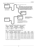
Страница 18: ...ble 5 for requirements Traps in refrigerant piping are required when elevation differences exist between evaporator and condensing unit mounting locations See Figure 12 for requirements Table 6 should be used when traps are required with field fabricated piping assemblies to calculate equivalent pipe lengths to determine if installation will comply with Table 5 requirements NOTE Proper safety equi...

Страница 19: ... 2 9 0 88 3 5 1 06 1 6 0 48 7 2 2 19 0 72 0 21 36 0 10 97 19 5 5 94 Refrigerant trap Four times equivalent length of pipe per this table Evaporator Evaporator Condensing Unit Condensing Unit NOTE When installing remote condensing units below the evaporator the suction gas line should be trapped with an inverted trap to the height of the evaporator This prevents refrigerant migration to the compres...

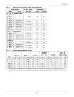
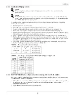
Страница 20: ...unit connection sizes Use Table 9 for recommended line sizes Prevailing good refrigeration practices should be employed for piping supports leak testing evacuation dehydration and charging of the refrigeration circuits The refrigeration piping should be isolated from the building by the use of vibration isolating supports Use a soft flexible material to pack around the tubes when sealing openings ...

Страница 21: ...41A _L7 PFHZ67A _L7 PFHZ66A _L7 51 11 23 45 10 12 Table 9 Recommended line sizes OD Cu Equiv ft m PFH_14A PFH_20A PFH_27A PFH_36A PFH_37A 3 ton circuit of 8 ton model PFH_42A PFH_41A PFH_67A PFH_66A 5 ton circuit of 8 ton model Suction Liquid Suction Liquid Suction Liquid Suction Liquid Suction Liquid Suction Liquid 50 15 2 5 8 3 8 5 8 3 8 7 8 3 8 7 8 1 2 7 8 1 2 1 1 8 1 2 75 22 9 5 8 3 8 7 8 3 8 ...

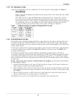
Страница 22: ...r if used refer to Table 12 2 5 5 R 407C PFH Installed as a Replacement Condensing Unit in an R 22 System When replacing the condensing unit of an existing Liebert split system containing R 22 and mineral oil the following should be considered 1 Check for proper operation of the system prior to replacing the outdoor unit If this is not possible at minimum perform a leak check to ensure that the co...

Страница 23: ... shorter interval replacements will be needed Optional Install a new filter drier approved for POE oil in place of the existing one Install the New Condensing Unit 1 Install a stub tube kit on the existing line set connecting to the new condensing unit This kit is available from Emerson or your local Emerson representative 2 Evacuate the evaporator piping system twice to a minimum 250 microns brea...

Страница 24: ...sing unit charges line sets and evaporator charges Total refrigerant charge evaporator lines condensing unit NOTE All condensing units and most evaporator units are fully charged with refrigerant Some evaporator units are shipped from the factory with a nitrogen holding charge only Refer to evaporator serial tags If field supplied refrigerant piping is installed refrigerant must be added to the sy...

Страница 25: ...tem pressures to determine whether the unit is operating properly NOTICE Risk of compressor slugging Can cause equipment damage Apply power to condenser 8 hours before operating the system This time is required to allow liquid refrigerant to be driven out of the compressor This is especially important at low ambient temperatures The compressor crankcase heater is energized as long as power is supp...

Страница 26: ...etween outdoor condensing unit and evaporator Table 16 Electrical data Standard sound and ambient models 95 F 35 C 60Hz Model Nominal Capacity Tons Electrical Characteristic Input Voltage Phase 208 230 1 208 230 3 460 3 575 3 14 1 FLA 9 1 WSA 11 0 OPD 15 20 1 5 FLA 12 1 WSA 14 8 OPD 25 27 2 FLA 13 4 WSA 16 4 OPD 25 37 3 FLA 18 5 13 4 7 1 5 8 WSA 22 8 16 4 8 7 7 0 OPD 35 25 15 15 42 3 5 FLA 15 0 7 ...

Страница 27: ... Table 18 Electrical data Quiet Line models 95 F 35 C 60Hz Model Nominal Capacity Tons Electrical Characteristic Input Voltage Phase 208 230 1 208 230 3 460 3 575 3 27 2 FLA 12 9 WSA 15 9 OPD 25 37 3 FLA 18 0 12 9 7 1 WSA 22 3 15 9 8 7 OPD 35 25 15 42 3 5 FLA 14 5 6 9 WSA 17 9 8 5 OPD 30 15 67 5 FLA 22 5 10 9 8 3 WSA 27 7 13 4 10 2 OPD 45 20 15 FLA Full Load Amps WSA Wire Size Amps minimum supply ...

Страница 28: ..._ 11 Control wiring connections completed ___ 12 All wiring connections are tight ___ 13 Foreign materials have been removed from area in and around all equipment installed shipping materials construction materials tools etc ___ 14 Fans and blowers rotate freely and in the proper direction ___ 15 Blank startup sheet has been sent with the evaporator unit and is ready to be completed by the install...

Страница 29: ...he alarm The control will turn off the LLSV and delay 10 seconds The control will permit this occurrence two more times or a total of three times If on the fourth try the high head pressure switch trips within 10 seconds the control will annunciate the alarm turn off the LLSV wait for the user to acknowledge the alarm and hold the compressor off for 3 minutes which is the normal short cycle contro...

Страница 30: ...quid quenching valve bulb must be located downstream of all these connections to control superheat at the compressor inlet Superheat settings for the liquid quenching valve are chosen to maintain consistency with the system expansion valve During hot gas bypass operation higher superheats 50 60 F 10 15 C may be observed at the compressor The liquid quenching valve is internally equalized and super...

Страница 31: ...s of the same system can usually be attributed to improper system cleaning NOTICE Risk of improper cleaning Can cause equipment damage Damage to a replacement compressor caused by improper system cleaning constitutes abuse under the terms of the warranty Before proceeding with a suspected burnout check all electrical components fuses contactors and wiring Check high pressure switch operation If a ...

Страница 32: ...ed recovery procedures and equipment Use a filter drier when charging the system with recovered refrigerant 4 Unsweat refrigerant connections and disconnect electrical connections 5 Remove failed compressor 6 Install replacement compressor and make all connections 7 Pressurize and leak test the system 8 Follow manufacturer s instructions for cleanout kits 9 Evacuate the system twice to a minimum 2...

Страница 33: ...ceiver NOTE The 5 ton high ambient 5 ton Quiet Line and 8 ton models consist of two condenser coils and two receivers When restricting airflow on these units the coils should be blocked off proportionally If one coil is restricted significantly more than the other liquid can remain in the restricted coil causing lower levels in the receivers The receiver liquid level should be above the sight glas...

Страница 34: ...sion valve for 10 15 F 5 6 to 8 4 C superheat at evaporator Defective liquid line solenoid valve Check valve and coil replace if necessary Low compressor capacity no cooling Defective liquid line solenoid valve Check valve and coil replace if necessary Plugged filter drier Check pressure drop across filter drier Replace filter drier Low refrigerant charge Check for normal system operating pressure...

Страница 35: ......
Страница 36: ...ebert monitoring emerson com 800 222 5877 Outside North America 00800 1155 4499 Single Phase UPS Server Cabinets liebert upstech emerson com 800 222 5877 Outside North America 00800 1155 4499 Three Phase UPS Power Systems 800 543 2378 Outside North America 614 841 6598 Environmental Systems 800 543 2778 Outside the United States 614 888 0246 Locations United States 1050 Dearborn Drive P O Box 2918...

Отзывы: