6 | EN
Copyright © Liberty Pumps, Inc. 2021 All rights reserved.
6850000D
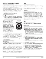
Seal Failure Probes
XLSG/XLSGX-Series grinder pumps are equipped with two
mechanical face seals with an intermediate oil chamber between
them. This ensures lubrication for the seals, shaft flame path, and
as a barrier to the motor chamber in the event the lower seal is
compromised. A seal fail or moisture sensing device is located in
the mid oil chamber and continuously monitors for leakage. In the
event of a seal failure, moisture mixes with the oil, tripping the
seal leak circuit. In a failure condition, a fault light will illuminate
on the control panel. The pump will continue to operate, but
service should be scheduled as soon as possible.
Intrinsically safe (ISS and ISD) control panels by Liberty Pumps
have a seal leak test button that tests the integrity of the seal leak
circuit continuity. When pressed, the light should illuminate. The
light should go off when the test button is released. If it remains
on, the potentiometer is set too high. If light does not illuminate,
the light is burned out, the circuitry is open, or the system does
not have power. The seal leak relay requires adjustment upon
installation. See Seal leak relay setup on page 8.
Seal fail probes connect to a relay in the control panel, which is
included in a Liberty Pumps control panel. For a non-Liberty
Pumps control panel or for a replacement relay, refer to Table 2.
Power and Control Cords
Do not remove cord and strain relief, and do not connect
conduit to pump.
The power and control cords cannot be spliced; a junction box
may be used providing it is rated for hazardous locations and has
approved cord connectors.
IMPORTANT:
Each cord has a green lead. This is the ground wire
and must be grounded properly per NEC
®
and/or local codes.
Wiring Instructions
Always disconnect pump(s) from power source(s) before
handling or making any adjustments to either the pump(s),
the pump system, or the control panel.
All installation and maintenance of pumps, controls,
protection devices, and general wiring shall be done by
qualified personnel.
All electrical and safety practices shall be in accordance with
the National Electrical Code
®
, the Occupational Safety and
Health Administration, or applicable local codes and
ordinances.
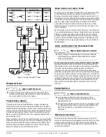
Figure 1. Wiring Diagram 1-Phase
Table 2. Seal Fail Replacement Relay
Description
Relay
Input
Voltage
Liberty
Pumps
P/N
Macromatic
P/N
Simplex, controls
1 pump
120V
K001672
SFP120A250
240V
K001673
SFP240A250
Duplex, controls
2 pumps
120V
K001675
SFP120C250
240V
K001676
SFP240C250
RISK OF ELECTRIC SHOCK
RISK OF ELECTRIC SHOCK
WHITE
WHITE
GREEN
BLACK
GREEN
GREEN
BLACK
GREEN
NOT
USED*
NOT
USED*
*
Note: on 1-phase pumps, the white and red leads of the
control cord are not used
SEAL
LEAK
BLACK
WHITE
RED
MOTOR
BLACK
WHITE
RED
RED
WHITE
GREEN
BLACK
L2/N
L1
RUN
CAP
START
CAP
POTTING
RESIN
SEAL
FAILURE
PROBES
START
RELAY
5 2
1
CONTROL
CORD
POWER
CORD
START CIRCUIT
START CIRCUIT


