-129-
v6.3
Working environment
•
The first part is the menu which allows configuration of general parameters such as the selected serial port.
•
The second part is a button menu which allows verification, opening, saving or loading the selected code on the board.
•
The third part contains the main code which will be loaded in Waspmote.
•
The fourth part shows us the possible compilation and load errors, as well as the success messages if the process is car-
ried out satisfactorily.
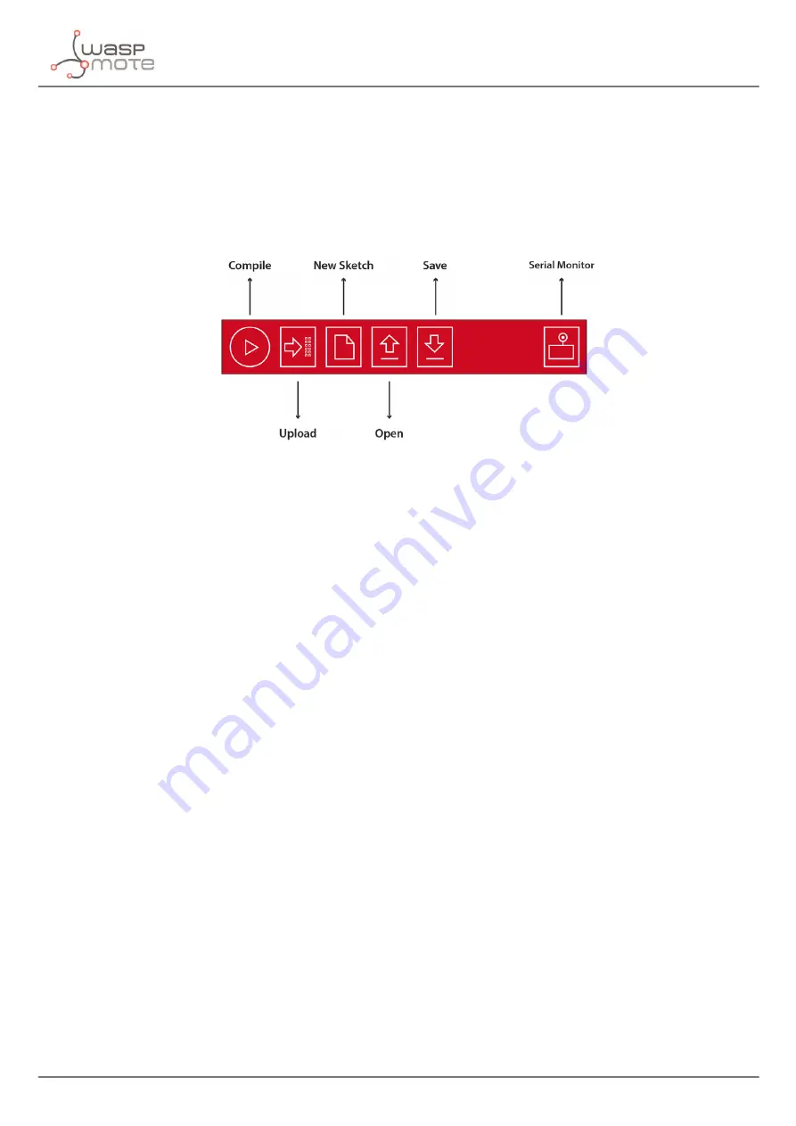
The Waspmote IDE buttons panel allows certain functions to be carried out such as opening a previously saved code, creating a
new one or loading the code on the board. The following figure shows the panel and the functions of each button.
Figure: IDE – Waspmote panel of buttons
Once the program has been opened correctly some configuration changes must be made so that the programs load correctly
in Waspmote.
In the
‘Tools/Board’
tab the Waspmote board must be selected. This refers to the API selected.
In the
‘Tools/Serial Port’
tab, the USB to which Waspmote has been connected to the computer must be selected.
Once these 2 parameters have been configured we can load a program onto Waspmote. The process will be explained using a
very simple example. A series of examples for learning and familiarizing yourself with the Waspmote environment have been
included in the downloaded file that contains the compiler.
The simplest example is the file called ‘test.pde’. In this example the text string “Hello World!” appears on the screen. The example
shows how to load a program onto Waspmote and how to show information on the screen.
The next step is to configure the folder where the created programs are going to be saved. In the Waspmote IDE this folder is
called
‘sketchbook’
and can be configured by accessing the
‘File/Preferences’
tab. Clicking on this tab will open a new window
where the location of the sketchbook can be indicated. Once the sketchbook folder path is indicated, the downloaded test
program must be saved in this folder.
Waspmote IDE must be closed so that the changes and the newly saved program in the sketchbook folder are reflected.
Run Waspmote again and open the downloaded test program by clicking on
‘Open’
.
Select the ‘test.pde’ file in the path where it has been unzipped and open it. As can be seen, it is a very simple code which lights
up a LED every 3 seconds and writes “Hello World!” on the screen.
The next step is to load the program onto Waspmote. To do this Waspmote must be connected to the computer through the
USB and the button
‘upload’
must be clicked. Then, it will start compiling the program. When the program has been compiled
correctly, a message will appear on the lower part of the window indicating this event. Conversely, if a fault occurs, red messages
will appear indicating the bugs in the code. When compiling is over, the code will be loaded onto Waspmote.
When the program has been loaded correctly, a message appears in the Waspmote window indicating
‘Done Uploading’
.
Conversely, if some problem occurs during loading, red messages will appear indicating the failures.
Once this program is loaded onto the board, the loaded code will run as was explained in the Architecture and System chapter.
Note:
The Gateway is just a UART-USB bridge. This means that the Gateway cannot be programmed and no code can not be uploaded.
Its function is to pass data from the XBee to the USB, and vice-versa.
Содержание Waspmote
Страница 1: ...Waspmote Technical Guide ...
Страница 11: ... 11 v6 3 Waspmote Kit Connect the battery in Waspmote Connect the sensor board Switch it on ...
Страница 59: ... 59 v6 3 Sensors Vibration Acceleration Free fall ...
Страница 79: ... 79 v6 3 LoRa Figure Channel frequencies in the 868MHz band Figure Channel frequencies in the 900MHz band ...
Страница 98: ... 98 v6 3 RFID NFC ...


