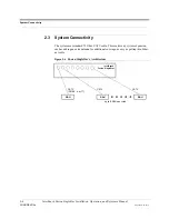


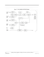


Fusion SingleStar Hub Rear Panel
3-8
InterReach Fusion SingleStar Installation, Operation, and Reference Manual
CONFIDENTIAL
D-620605-0-20 Rev A
3.2.1
Fusion SingleStar Hub Rear Panel Connectors
3.2.1.1
9-pin D-sub Connector
The 9-pin D-sub connector (labeled
DIAGNOSTIC 1
) provides a contact alarm for fault
and warning system alarm monitoring.
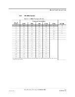
Table 3-3 lists the function of each pin on the 9-pin D-sub connector.
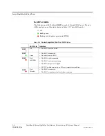
Table 3-3
9-pin D-sub Pin Connector Functions
This interface can both generate two source contact alarms (Fault and Warning) and
sense 3 single external alarm contacts (Alarm Sense Input 1 through 3).
3.2.1.2
N-type Female Connectors
There are two N-type female connectors on the rear panel of the Hub:
• The
DOWNLINK
connector receives downlink RF signals from a repeater, local
base station, or MetroReach Focus system.
• The
UPLINK
connector transmits uplink RF signals to a repeater, local base sta-
tion, or MetroReach Focus system.
CAUTION:
The
UPLINK
and
DOWNLINK
ports cannot handle a DC power
feed from the local base station. If the DC power is present, a DC block must
be used or the Fusion SingleStar hub may be damaged.
Pin
Function
1
Alarm Sense Input Ground
2
Alarm Sense Input 3
3
Alarm Sense Input 2
4
Warning Source Contact (positive connection)
5
Warning Contact (negative connection)
6
DC Ground (common)
7
Fault Source Contact (positive connection)
8
Alarm Sense Input 1
9
Fault Source Contact (negative connection)
Содержание InterReach Fusion SingleStar
Страница 1: ...D 620605 0 20 Rev A Installation Operation and Reference Manual InterReach Fusion TM SingleStar ...
Страница 2: ...D 620605 0 20 Help Hot Line U S only 1 800 530 9960 Rev A CONFIDENTIAL ...
Страница 150: ...A 4 InterReach Fusion SS Installation Operation and Reference Manual CONFIDENTIAL D 620605 0 20 Rev A ...