background image

A9

Control Function

Control Panel Functions

This Indicator lights up blue when the display
operates normally(On Mode). If the display is in Sleep
Mode (Energy Saving), this indicator color changes 
to amber.

Use this button to turn the display on or off.

Power Button

Power Indicator

Use this button to enter a selection in the On Screen 
Display.

AUTO/SET
Button

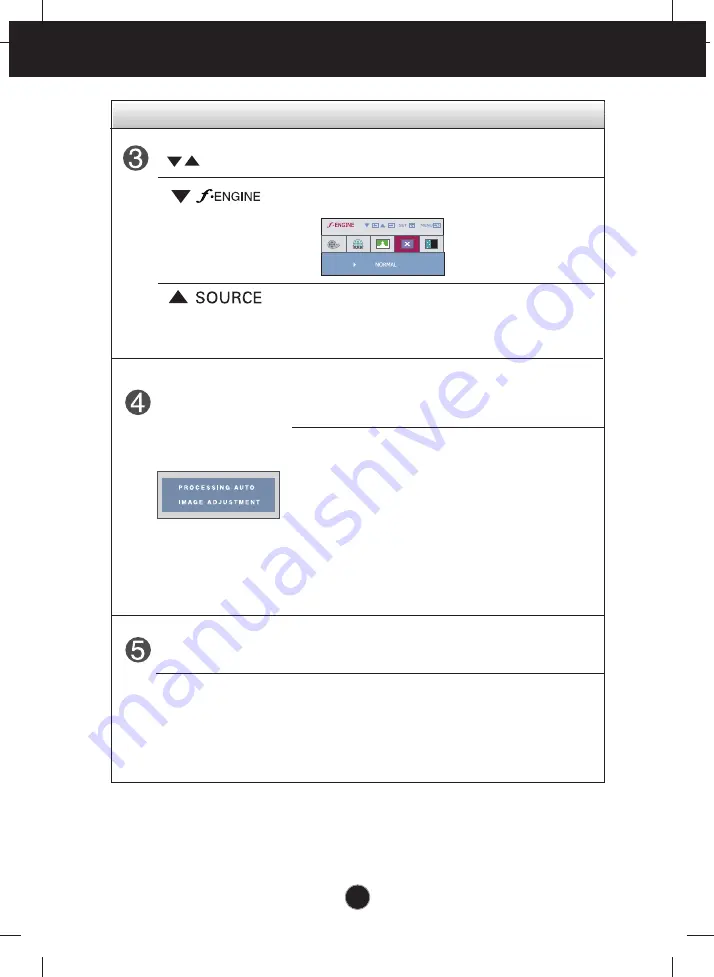
AUTO IMAGE ADJUSTMENT

When adjusting your display settings, always press
the 

AUTO/SET

button before entering the On Screen

Display(OSD). This will automatically adjust your
display image to the ideal settings for the current
screen resolution size (display mode).

The best display mode is

- W1942PE : 

1440 x 900

Buttons

Use these buttons to select or adjust functions in the
On Screen Display.

For more information, refer to page A16.

Use this button to make D-Sub or DVI connector
active. This feature is used when two computers are
connected to the display. The default setting is D-Sub.

Содержание W1942HEU

Страница 1: ...t Precautions before using the product Keep the User s Guide CD in an accessible place for future reference See the label attached on the product and give the information to your dealer when you ask for service W1942PE User s Guide ...

Страница 2: ...ower cords and broken plugs They may result in a shock or fire hazard Call your service technician for replacement Do not Open the Display There are no user serviceable components inside There are Dangerous High Voltages inside even when the power is OFF Contact your dealer if the display is not operating properly To Avoid Personal Injury Do not place the display on a sloping shelf unless properly...

Страница 3: ...use some afterimages Some dot defects may appear as Red Green or Blue spots on the screen However this will have no impact or effect on the display performance If possible use the recommended resolution to obtain the best image quality for your LCD display If used under any mode except the recommended resolution some scaled or processed images may appear on the screen However this is characteristi...

Страница 4: ...ence to radio communications However there is no guarantee that interference will not occur in a particular installation If this which can be determined by turning the equipment off and on the user is encouraged to try to correct the interference by one or more of the following measures Reorient or relocate the receiving antenna Increase the separation between the equipment and the receiver Connec...

Страница 5: ...ed devices is turned off Connecting the stand 1 Place the monitor with its front facing downward on a cushion or soft cloth 2 Assemble the Stand Base into the Stand Body Be sure don t pull out the Stop Pin and make the Stand Base direction as shown 3 Make the monitor stand then pull out the Stop Pin Stand Base FRONT Stand Body Stop Pin Side Stop Pin Stop Pin pull out the stop pin The tape and lock...

Страница 6: ...itioning your display 1 Adjust the position of the panel in various ways for maximum comfort Tilt Range 6 17 Swivel 356 Ergonomic It is recommended that in order to maintain an ergonomic and comfortable viewing position the forward tilt angle of the monitor should not exceed 5 degrees Height Range maximum 4 33 inch 110 0 mm 110 0 mm First remove the locking pin ...

Страница 7: ...0o clockwise Please be cautious and avoid contact between the monitor head and the Stand Base when rotating the screen to access the Pivot function If the monitor head touches the Stand Base then the Stand Base could crack 3 For detailed information please refer to the Pivot Software CD provided UsingthePivotfunction Stand section Head section ...

Страница 8: ...tor the computer system and other attached devices is turned off Positioning your display Using the cable holder 1 2 3 If you want to use the cable holder to let your cables together please put them through right as shown For if you don t do like that you cannot use Pivot function smoothly ...

Страница 9: ...Thisfeatureisnotavailableinallcountries NOTE Self Image Setting Function This function provides the user with optimal display settings When the user connects the monitor for the first time this function automatically adjusts the display to optimal settings for individual input signals AUTO SET Function When you encounter problems such as blurry screen blurred letters screen flicker or tilted scree...

Страница 10: ...ertently changed Press and hold the MENU button for several seconds The message OSD LOCKED should appear You can unlock the OSD controls at any time by pushing the MENU button for several seconds The message OSD UNLOCKED should appear Front Panel Controls 4 3 in Wide To select the image size of the screen WIDE 4 3 WIDE Switch to full screen mode according to input image signal 4 3 Change the image...

Страница 11: ...E ADJUSTMENT When adjusting your display settings always press the AUTO SET button before entering the On Screen Display OSD This will automatically adjust your display image to the ideal settings for the current screen resolution size display mode The best display mode is W1942PE 1440 x 900 Buttons Use these buttons to select or adjust functions in the On Screen Display For more information refer...

Страница 12: ...he OSD To make adjustments in the On Screen Display follow these steps Press the MENU Button then the main menu of the OSD appears To access a control use the or Buttons When the icon you want becomes highlighted press the AUTO SET Button Use the Buttons to adjust the image to the desired level Use the AUTO SET Button to select other sub menu items Push the MENU Button once to return to the main m...

Страница 13: ...just the position of the screen To customize the color of the screen To customize the screen status for a user s operating environment To improve the clarity and stability of the screen BRIGHTNESS CONTRAST GAMMA HORIZONTAL VERTICAL CLOCK PHASE SHARPNESS WHITE BALANCE POWER INDICATOR FACTORY RESET LANGUAGE OSD HORIZONTAL POSITION VERTICAL sRGB 6500K 9300K Adjustable A Analog Input D Digital Input T...

Страница 14: ...oduced to the procedure of selecting and adjusting an item using the OSD system Listed below are the icons icon names and icon descriptions of the all items shown on the Menu Press the MENU Button then the main menu of the OSD appears Sub menus Menu Name Icons Main Menu Button Tip MENU Exit Adjust Decrease Increase SET Enter Select another sub menu ...

Страница 15: ...tish images and low gamma values display blackish images PICTURE PRESET RED GREEN BLUE Select the screen color sRGB Set the screen color to fit the SRGB standard color specification 6500K Slightly reddish white 9300K Slightly bluish white Set your own red color levels Set your own green color levels Set your own blue color levels COLOR PICTURE COLOR MENU Exit Decrease Increase SET Select another s...

Страница 16: ...ze any vertical bars or stripes visible on the screen background The horizontal screen size will also change To adjust the focus of the display This item allows you to remove any horizontal noise and clear or sharpen the image of characters To adjust the clearness of the screen HORIZONTAL VERTICAL To move image left and right To move image up and down TRACKING TRACKING ...

Страница 17: ...If the output of the video card is different the required specifications the color level may deteriorate due to video signal distortion Using this function the signal level is adjusted to fit into the standard output level of the video card in order to provide the optimal image Activate this function when white and black colors are present in the screen POWER INDICATOR Restore all factory default ...

Страница 18: ...er normal operating conditions This is just for advertising to customer in the shops It s setting is same with Movie mode and screen is divided by half This feature lets you easily select the best desired image condition optimized to the environment ambient illumination image types etc User You can manually adjust brightness ACE or RCM You can save or restore the adjusted value even when using a d...

Страница 19: ...er saving mode try moving the mouse or pressing any key on the keyboard to bring up the screen Try to turn on the PC This message appears when the signal from the PC video card is out of horizontal or vertical frequency range of the display See the Specifications section of this manual and configure your display again This message appears when the signal cable between your PC and your display is n...

Страница 20: ...setting If the results are unsatisfactory decrease the horizontal bars using the PHASE icon in the on screen display Check Control Panel Display Settings and adjust the display to the recommended resolution or adjust the display image to the ideal setting Set the color setting higher than 24 bits true color Important Check Control Panel Display Settings and see if the frequency or the resolution w...

Страница 21: ...bits true color at Control Panel Settings Check if the screen is set to interlace mode and if yes change it to the recommend resolution Do you see an Unrecognized monitor Plug Play VESA DDC monitor found message Have you installed the display driver Be sure to install the display driver from the display driver CD or diskette that comes with your display Or you can also download the driver from our...

Страница 22: ...e SOG Sync On Green Digital HDCP Signal Input 15 pin D Sub Connector DVI D Connector Digital Input Form RGB Analog 0 7 Vp p 75 ohm Digital Max Analog VESA 1440 x 900 75 Hz Digital VESA 1440 x 900 60 Hz Recommend VESA 1440 x 900 60 Hz DDC 2B On Mode 22W Typ Sleep Mode 0 3 W Off Mode 0 3 W With Stand Without Stand Width 44 84 cm 20 30 inches 44 84 cm 20 30 inches Height 40 14 cm 15 80 inches 30 06 c...

Страница 23: ...600 800 x 600 832 x 624 1024 x 768 1024 x 768 1152 x 870 1152 x 900 1280 x 1024 1280 x 1024 1440 x 900 1440 x 900 1440 x 900 31 469 31 468 31 469 37 500 37 879 46 875 49 725 48 363 60 123 68 681 61 805 63 981 79 976 55 500 55 935 70 635 70 70 60 75 60 75 75 60 75 75 65 60 75 60 60 75 Recommend Mode Only Analog Mode W1942PE Indicator On Mode Sleep Mode Off Mode blue amber Off LED Color MODE ...

Страница 24: ...r firstly separating 4 screws by using a driver as figure 3 Install the Wall mount plate Wall mount plate Separate purchase This is stand type or wall mount type and is connectable with Wall mount plate Please refer to the installation guide for more details which is provided when Wall mount plate is purchased Kensington Security Slot Connected to a locking cable that can be purchased separately a...

Страница 25: ...Digitally yours ...

Отзывы: