


2-43
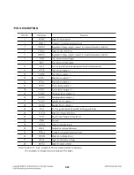
MIC_MCLK
30
O
Main clock for external microphone input A/DC.
Clock frequency can be selected between 6.144MHz,
12.288MHz, and 24.576MHz.
MIC_BCK
31
I/O
PCM bit clock input/output of external microphone.
Bit clock frequency is 3.072MHz (48kHz x 64, fixed)
MIC_LRCK
32
I/O
PCM Word clock (left-right clock) input/output of external
microphone. Word clock rate is 48kHz (fixed).
MIC_SDIN
33
I
PCM serial data input of external microphone.
Schmitt-Trigger input.
DMIX_MCLK
93
O
Main clock for external down-mix line output D/AC.
DMIX_BCK
89
O
PCM bit clock output of down-mix signal.
Bit clock frequency is 6.144MHz (96kHz x 64, fixed)
DMIX_LRCK
88
O
PCM Word clock (left-right clock) output of down-mix signal.
Word clock rate is 96kHz (fixed).
DMIX_SDOUT 90
O
PCM
serial
data output of down-mix signal.
PWM Audio Output
PWM1_P
49
O
Positive PWM output of channel 1.
PWM1_M 48 O
Negative PWM output of channel 1.
PWM2_P
52
O
Positive PWM output of channel 2.
PWM2_M 51 O
Negative PWM output of channel 2.
PWM3_P
55
O
Positive PWM output of channel 3.
PWM3_M 54 O
Negative PWM output of channel 3.
PWM4_P
59
O
Positive PWM output of channel 4.
PWM4_M 58 O
Negative PWM output of channel 4.
PWM5_P
62
O
Positive PWM output of channel 5.
PWM5_M 61 O
Negative PWM output of channel 5.
PWM6_P
68
O
Positive PWM output of channel 6.
PWM6_M 67 O
Negative PWM output of channel 6.
PWM7_P
71
O
Positive PWM output of channel 7.
PWM7_M 70 O
Negative PWM output of channel 7.
PWM8_P
75
O
Positive PWM output of channel 8.
PWM8_M 74 O
Negative PWM output of channel 8.
PWM_HP_L_P
46
O
Positive PWM output of headphone left channel.
PWM_HP_L_M
45
O
Negative PWM output of headphone left channel.
PWM_HP_R_P
41
O
Positive PWM output of headphone right channel.
PWM_HP_R_M
40
O
Negative PWM output of headphone right channel.
PWM_SWL_P 37
O
Positive PWM output of subwoofer line output.
PWM_SWL_M 36
O
Negative PWM output of subwoofer line output.
System Control Interface
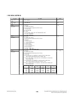
SPI/I2C
84
I
Host interface mode (SPI or I2C) selector.
Assert ‘HIGH’ for SPI mode. De-assert ‘LOW’ for I2C mode.
Internal pull-down resistor.
SO/SDA
78
I/O
SO for SPI mode or SDA for I2C mode.
Содержание SH33SD-S
Страница 25: ...2 16 4 SLED CONTROL RELATED SIGNAL NO DISC CONDITION FIG 4 1 1 2 3 4 1 2 3 4 ...
Страница 27: ...2 18 FIG 7 2 DVD 7 DISC TYPE JUDGEMENT WAVEFORMS FIG 7 1 DVD 1 2 3 IC501 IC501 1 2 3 1 2 3 ...
Страница 28: ...2 19 FIG 7 4 CD FIG 7 3 CD 1 2 3 IC501 IC501 1 2 3 1 2 3 ...
Страница 29: ...2 20 FIG 8 2 CD 8 FOCUS ON WAVEFORMS FIG 8 1 DVD 1 2 3 1 2 3 4 4 1 2 4 3 IC501 ...
Страница 31: ...2 22 11 MT1389 L VIDEO OUTPUT WAVEFORMS 1 Full colorbar signal COMPOSIT FIG 11 1 FIG 10 2 CD 3 4 2 1 1 2 4 1 3 ...
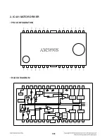
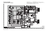
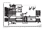
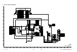
Страница 41: ...2 32 2 IC401 MOTOR DRIVER PIN CONFIGURATION BLOCK DIAGRAM ...
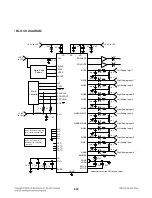
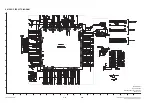
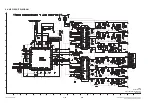
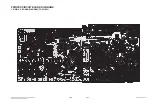
Страница 42: ...2 33 1 IC501 MPEG MT1389L PIN DESCRIPTION ...
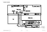
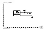
Страница 54: ...2 45 2 46 WIRING DIAGRAM PN202 CABLE1 18PIN WIRING DIAGRAM HT303 HT353 EBY38558901 8 REV 8 2 2008 12 16 ...
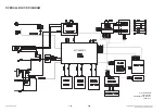
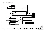
Страница 55: ...2 47 2 48 OVERALL BLOCK DIAGRAM MT1389FE L BLOCK DIAGRAM HT303 HT353 EBY38558901 7 REV 8 2 2008 12 16 ...
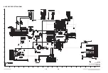
Страница 66: ...2 69 2 70 PRINTED CIRCUIT BOARD DIAGRAMS 1 MAIN P C BOARD DIAGRAM TOP VIEW ...
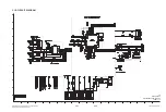
Страница 67: ...2 71 2 72 MAIN P C BOARD DIAGRAM BOTTOM VIEW ...
Страница 74: ...2 PASSIVE SUBWOOFER SH33SD W 950 A90 951 953 956 954 952 955 WIRE90 3 7 ...
Страница 75: ......


