


- 13 -
ADJUSTMENT INSTRUCTIONS
6. Component 2 Offset Adjustment
6-1. Required Test Equipment
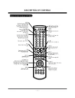
Remote control for adjustment, 802F
6-2. Preparation for Adjustment
(1) Connect a power source with TV Set and turn TV Set on.
(2) Run the unit in "Heat Run" mode for 15 min and over before
adjustment.
(3) Receive the Component 2 signal.
(4) Receive the 720P and HozTVBar Pattern of 802F.
6-3. Offset Adjustment
(1) Press ADJ key on the Remote Control to enter the adjustment
mode after more than 10 seconds of receiving the signals.
(2) Press the Enter key in 3. AD9883-set of adjustment item to
adjust automatically.
(3) When the adjustment is completed, enter the adjustment
mode by pressing Enter key after appearing “ Adjustment
Completion(Press the Enter)” OSD.
7. Adjustment of White Balance and Gamma
7-1. Required Test Equipments
(1) Illuminometer (name of model : CA-100) 1EA —> Measure
color of projecting screen center
[
CA-110(name of model) is possible to measure White
Balance and Gamma —- leave it 20Cm from screen center
Follow a measurement machine manual to set CA-100 and
CA-110 measurement machine.
(2) Pattern Generator 1EA —> 16 step Gray Pattern, 64 step
Gray Pattern
(3) Set Fixation Stand 1EA
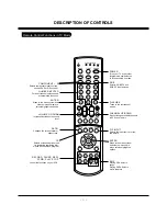
(4) Remote Control 1EA
7-2. Preparation for Adjustment
(1) Select the VDP Test Pattern signal to R1, G1, B1.
(2) Press the Instart key to select 1. LCD --> 2. 62352 and then
select 5. RVREF, 8. GVREF, 12. BVREF in adjust mode.
(3) Adjust the luminance of CA100 below 0.75Cd. (The adjust-
ment range is 196~202)
(4) Exit adjustment mode by pressing ENTER button on Remote
Control.
(5) Select 3. 7050 RGB Set in adjustment mode.
(6) Check the data 1. RContrast, 8. GContrast, 15. BContrast is
515. Otherwise set the data 515 by using volume button.
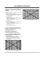
7-3. Adjustment Sequence
(1) Output the 255,255,255 signal of VDP Test Pattern, then dis-
play the maximum white pattern on screen.
(2) Gamma Adjust Mode is display as below when select 4.
Gamma adjust by selecting ADJ key on R/C.
(3) Change the 16 Step RGB Data to select white balance
x=283, y=297(D9300K).
(4) Measure the luminance with changed data.
(5) Set the every Gamma data of 16 step to 2.2 on the basis of
measured luminance data in 3).
(Max luminance *(n1/16)**2.2) — Max luminance : measured
luminance data n1 = every step unit when separating signal
level to 16 step)
(6) Output the 240, 240, 240(15th data in max white output signal
level) in the VDP Test Pattern, change the 15th RGB Data
value to come out white balance x=283, y=297(D9300K) and
measured step luminance in 5).
(7) Output the 224, 224, 224(14th data in max white output signal
level) in the VDP Test Pattern, change the 14th RGB Data
value to come out white balance x=283, y=297(D9300K) and
measured step luminance in 5).
(8) As shown above, output the VDP Test Pattern sig-
nal(208/192/176/160/144/128/112/96/80/64/48/32/16) and
change the RGB Data value of each step to come out white
balance x=283, y=297(D9300K) and measured luminance in
3).
7-4. Gamma adjustment manually
This adjustment is only to be done after the Gamma and White
Balance adjustments are adjusted.
(1) Prepare the PC Pattern Generator which is possible to output
R/G/B of 16 step and 64 step Gray Pattern.
(2) Equipment composition : Follow Fig. 2.
(3) Turn on the Jig for adjustment.
(4) Select the RGB_PC by pressing the input select button on
Remote Control.
(5) Output the 16 Gray Pattern in PC Pattern Generator.
Check it with the naked eye whether Screen Gamma and W/B
is right about each Gray.
If it’s not, press the ADJ button on Remote Control and then
adjust the level data of each step manually in sub menu of 4.
Gamma Manual adjust.
(6) Output the 64 Gray Pattern in PC Pattern Generator.
Check it with the naked eye whether Screen Gamma and W/B
is right about each Gray or whether there is Gamma noise.
If there’s any problem, adjust in 5).
(7) After finishing adjustment, exit adjustment mode by using
ADJ button on Remote Control.
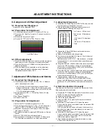
HozTVBar Pattern
Gamma Adjust Mode
1
2
3
16
80
234
453
724
100
216
411
740
RGB 456 Step123
100
216
387
780
* 1st Column : 16 Step Level
* 2nd Column : R Adjustment
Data
* 3rd Column : G Adjustment
Data
* 4th Column : B Adjustment
Data
Содержание RU-44SZ80L - - 44" Rear Projection TV
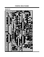
Страница 15: ... 15 PRINTED CIRCUIT BOARD MAIN TOP ...
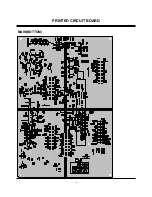
Страница 16: ... 16 PRINTED CIRCUIT BOARD MAIN BOTTOM ...
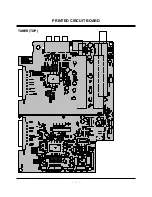
Страница 17: ... 17 PRINTED CIRCUIT BOARD TUNER TOP ...
Страница 18: ... 18 PRINTED CIRCUIT BOARD TUNER BOTTOM ...
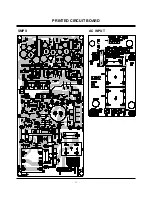
Страница 19: ... 19 PRINTED CIRCUIT BOARD DRIVER TOP ...
Страница 20: ... 20 PRINTED CIRCUIT BOARD DRIVER BOTTOM ...
Страница 21: ... 21 PRINTED CIRCUIT BOARD DIGITAL TOP ...
Страница 22: ... 22 PRINTED CIRCUIT BOARD DIGITAL BOTTOM ...
Страница 23: ... 23 PRINTED CIRCUIT BOARD SMPS AC INPUT ...
Страница 24: ... 24 PRINTED CIRCUIT BOARD SIDE A V CRM TOP CRM BOTTOM ...
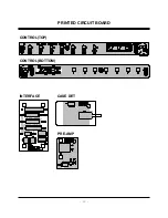
Страница 25: ... 25 CASE DET PRE AMP INTERFACE CONTROL TOP CONTROL BOTTOM PRINTED CIRCUIT BOARD ...
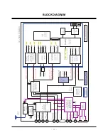
Страница 26: ... 26 BLOCK DIAGRAM ...
Страница 27: ... 27 NOTES ...
Страница 40: ......
Страница 41: ......
Страница 42: ......
Страница 43: ......


