


- 17 -
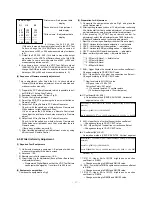
* First column : R adjustment data
display
* Second column : G adjustment
data display
* Third column : B adjustment data
display
6) Output the 240, 240, 240
(15th data in max white output signal level) in the VDP Test
Pattern, change the 15th RGB data value to come out
white valance x=283, y=294 and measured step luminance
in 5).
7) Output the 240, 240, 240 (14th data in max white output
signal level) in the VDP Test Pattern, change the 14th RGB
data value to come out white valance x=283, y=294 and
measured step luminance in 5).
8) As shown above, output the VDP Test Pattern signal
(208/192/176/160/144/128/112/96/80/64/48/32/16) and
change the RGB data value of each step to come out white
balance x=283, y=294 and measured luminance in 3).
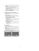
(5) Sequence of Gamma manually adjustment
This is adjustment (after finish the 3-4) to check whether
Gamma/ White balance adjustment are well adjusted and
make correction manually.
1) Prepare the PC Pattern Generator which is possible to out-
put R/G/B of 16 step Gray Pattern.
2) Equipment composition : Follow <Fig. 2>.
3) Turn on the Jig for adjustment.
4) Select the RGB_PC by pressing the input select button on
Remote Control.
5) Output the 16 Gray Pattern in PC Pattern Generator.
Check it with the naked eye whether Screen Gamma and
White balance is right about each Gray.
If it’s not, press the ADJ button on Remote Control and
then adjust the level data of each step manually.in “Gamma
adjust”.
6) Output the 64 Gray Pattern in PC Pattern Generator.
Check it with the naked eye whether Screen Gamma and
White balance is right about each Gray or whether there is
Gamma noise.
If there’s any problem, adjust in 5)
7) After finishing adjustment, exit adjustment mode by using
ADJ button on Remote Control.
6-5. White Uniformity Adjustment
(1) Required Test Equipments
1) Uniformity measuring equipment : Equipment which can
measure chromatiity in the whole screen
2) Set stand : 1EA
3) Remote controller for adjustment : 1EA
4) Circuit thing Jig for Adjustment (Except Driver Board Assy
of adjustment model)
--- Programmed Digital Board so that the VDP Test Pattern
can output white signal by 1level form 0 to 255 level.
(2) Equipment composition
Compose the equipment as Fig.2
(3) Preparation for Adjustment
1) Composite the equipment as shown Fig.2, and place the
set on fixation stand.
2) After inputting company channel 13, adjust colour uniformity
like Horizontal/ Vertical position adjustment of input signal
part adjustment by using remote control for adjustment.
3) After pressing IN_START key on remote control for
adjustment, select the adjustment mode 7050 Uniformity.
<Resister Explanation about uniformity adjustment>
1. RamCtrl : s/w saving uniformity write order (Do not adjust)
2. CSHP : Horizontal start point designation --- adjustable
3. CSVP : Vertical start point designation --- adjustable
4. CEHP : Horizontal END point designation --- adjustable
5. CEVP : Vertical END point 6.designation --- adjustable
6. Mode : uniformity mode select --- adjustable if need
*** 0 : 221point & 3level ---- defalut value
*** 1 : 221point & 4level
*** 2 : 825point & 3level
*** 3 : 825point & 4level
7. KHH : Upper 2byte of horizontal line correction coefficient --
Change according to CSHP, CEHP value.
8. KHL : Upper 2byte of vertical line correction coefficient --
Change according to CSHP, CEHP value.
** How to calculate KHH, KHL value
LCD panel size = 1280 x 720
Correction Point = 221 point
--> 17 horizontal points x 13 vertical points
(16 horizontal segments x 12 vertical poins)
O
H Coefficient(KHH, KHL)
--> Calculation method (CEHP-CSHP=1280, Horizontal
segment value =16)
9. KVH : Upper 2byte of vertical line correction coefficient
-- Change according to CSVP, CEVP value.
10. KVL : Upper 2byte of vertical line correction coefficient
-- Change according to CSVP, CEVP value.
O
V Coefficient(KVH, KVL)
Calculation method (CEVP-CSVP=720, Vertical segment
value =12)
11. RL1H : Upper 9bit of MID2 brightness correction
coefficient in R MIN.
--- Change according to RMIN and RMID2 value.
12. RL1L : Lower 9bit of MID2 brightness correction coefficient
in R MIN.
--- Change according to RMIN and RMID2 value.
13. RL2H : Upper 9bit of MID1 brightness correction
coefficient in R MID2.
--- Change according to RMID2 and RMID1 value.
H coefficient = 1/(number of pixel intervals between setting in the horizontal
direction)
Hcoeff = 1/((1280/16)-1) = 0.012658227
hex (0.012658227 x 2
16
) = 0 x 033D, Hcoeff (hex) = 0 x 033D + 1 = 0 x 33E
V coefficient = 1/(number of pixel intervals between setting in the vertical
direction)
Vcoeff = 1/((720/12)-1) = 0.016949152
hex (0.016949152 x 2
16
) = 0 x 0456, Vcoeff (hex) = 0 x 0456 + 1 = 0 x 0457
Gamma Adjust
R:1
G:2
B:3
80
100
100
234
216
216
453
411
387
--------------------------
--------------------------
724
690
780
Содержание RT-52SZ30RB
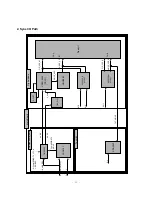
Страница 24: ... 24 5 General Control Signal ...
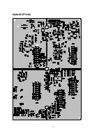
Страница 25: ... 25 PRINTED CIRCUIT BOARD MAIN TOP ...
Страница 26: ... 26 MAIN BOTTOM ...
Страница 27: ... 27 COMPONENT TOP COMPONENT BOTTOM SIDE A V PRE AMP LED AC INPUT ...
Страница 28: ... 28 LCD DRIVER TOP CONTROL ...
Страница 29: ... 29 LCD DRIVER BOTTOM ...
Страница 30: ... 30 DIGITAL BOTTOM DIGITAL BOTTOM ...
Страница 31: ... 31 TUNER TOP TUNER BOTTOM ...
Страница 32: ... 32 SMPS POWER S W INTERFACE BALLAST ...
Страница 33: ...MEMO 33 ...
Страница 46: ...P No 3854VA0117A S1 1 2 2003 6 21 ...
Страница 47: ...P No 3854VA0117A S1 2 2 2003 6 21 ...
Страница 48: ...P No 3854VA0117A S2 1 2 2003 6 21 ...
Страница 49: ...P No 3854VA0117A S2 2 2 2003 6 21 ...
Страница 50: ...SVC SHEET 3854V A0117A S1 SVC SHEET 3854V A0117A S2 SVC SHEET ...