* RF AGC (Auto Gain Control) A djustmen
t
The RF AGC contro l
(VR101)
was aligned at the time of manufacture for optimum performance over a wide range
conditions. Readjust of VR101 should not be necessary unless unusual local conditions exist, such as ;
1) Channel interference in a CATV system
2) Picture bending and/or color beats, which are unusually due to excessive RF signal input when the receiver is too close
to a transmitting tower or when the receiver is connected to an antenna distribution system where the RF signal has
been amplified.
In this case, the input signal should be attenuated (with pad or filter) to a satisfactory level.
3) Picture noise caused by “broadcast noise” or weak signal.
If the broadcast is “clean” and the RF signal is at least 1mV (60dBu), the picture will be noise free in any area.
Adjusting th e
VR101 (RF AGC)
control to one end of rotation will usually cause a relatively poor signal to noise ratio;
Adjusting to the other end of rotation will usually cause a degradation of over load capabilities resulting in color beats or
adjacent channel reference.
For best results, adjust
VR101
control while performing on all other local channels, or the voltage at J173 will be 6.0+_0.1Vdc.
(RF level: 60dBuV).
* Focus A djustment
NOTE : This adjustment should be performed after warming up for 10 minutes.
1) Set color & brightness to minimum, contrast to 50% respectively.
2) Input the PAL BG Digital Pattern signal.
3) Adjust the Focus control for best overall focus.
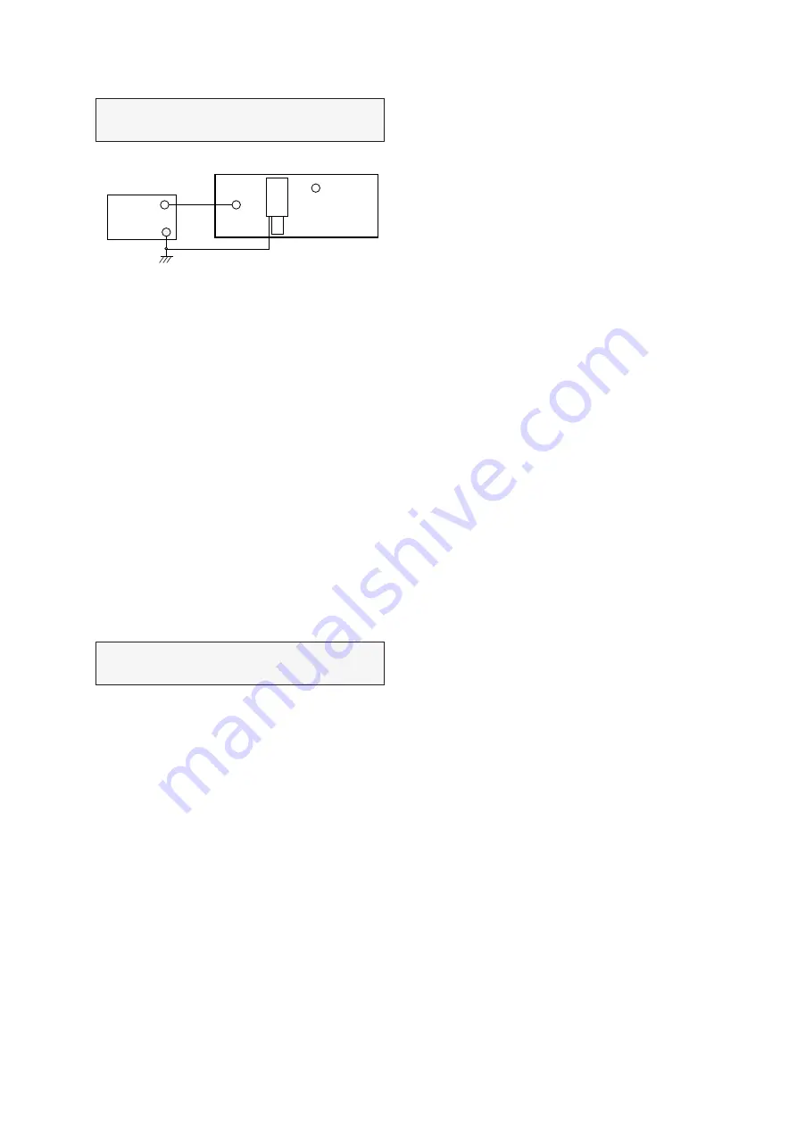
Test Poin t :
J173 or Observing Display
Adjus t :
VR101
J173
6Vdc
AGC TP.
VR101
(AGC ADJ.)
Digital
Multimeter
MAIN BOARD
TUNER
Fig. 5
Test Poin t :
Observing Display
Adjus t :
Focus control of FBT