background image

7

Connecting to External Devices

1

2

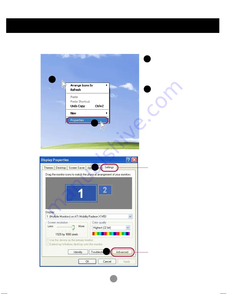
Move the mouse pointer to an
empty area on the Windows
screen (with no icons or task
bars) and click the right
mouse button.

1

2

When the pop-up menu
appears, click the
'

Properties

' menu.

4.

1

Select '

Settings'

tab.

2

Click '

Advanced

' button.

5.

Содержание M4210D

Страница 1: ...t Keep the User s Guide CD in an accessible place for furture reference See the label attached on the product and give the information to your dealer when you ask for service M4210D User s Guide Warranty void if removed Important WARRANTY VOID IF REMOVED 3850TAZ209Y ...

Страница 2: ...scopic images See if the resolution is set to Full HD The recommended resolution for 3D images is 1920X1080 If a viewer moves left or right with a distance of more than 4 m the screen might look dimmed Keep a distance of more than 4 m from the product 4 m Falls kein 3D Video genutzt wird erscheint der Bildschirm verzerrt Installing the 3D Player To enjoy the 3D video To view the applicable Guide c...

Страница 3: ...wn buttons Bring up and down direction adjustment ARC button To select the image size of the screen Auto Button Automatic adjustment function Operational for the analog signal only Exit Button There is not a function which is supported There is not a function which is supported CTR PWR Button Turn on the power of the PC built in the monitor and then turn off The CTR PWR function operates only when...

Страница 4: ...gnal type you want using the button Input Select Button Using the Remote Control 1 Take out the battery cap 2 Insert the batteries with correct polarity 3 Close the battery cap Dispose of used batteries in the recycle bin to prevent environmental pollution Inserting batteries into remote control RGB DVI INPUT AAA Type ...

Страница 5: ...g terminal of the PC sound card is checked before connecting If the Audio Out of PC sound card has only Speaker Out reduce the PC volume If the Audio Out of the PC sound card supports both Speaker Out and Line Out convert to Line Out using the card jumper of the program Refer to the Sound Card Manual The product image in the user s guide could be different from the actual image OUT IN RGB IN RGB O...

Страница 6: ...power cord 1 5 When connecting with the DVI signal input cable Turn on power by pressing the power button on the product ON OFF AUTO SET SOURCE Power button Select DVI DVI Digital signal Install the driver files contained at the supplied CD 2 3 4 Select an input signal Press the INPUT button on the remote control to select the input signal Or press the SOURCE button at the back side of the product...

Страница 7: ...ower button 3 When connecting with the D Sub signal input cable OUT IN RGB IN RGB OUT DVI IN REMOTE CONTROL IN RS 232C CONTROL SERVICE AUDIO RGB DVI LAN RGB OUT SERLAL PORT USB H PHONE OUT SP DIF RGB IN RGB OUT Rear side of the product Connect the power cord Install the Video driver file contained at the supplied CD 1 ...

Страница 8: ...1 2 Move the mouse pointer to an empty area on the Windows screen with no icons or task bars and click the right mouse button 1 2 When the pop up menu appears click the Properties menu 4 1 Select Settings tab 2 Click Advanced button 5 ...

Страница 9: ...8 Connecting to External Devices 6 Select CATALYST R Control Center tab Click ATI CATALYST R Control Center button 1 2 1 2 Select Display Manager menu Select Detect Displays button 7 ...

Страница 10: ...GB DVI INPUT INPUT SET SOURCE AUTO SET How to connect to two computers Connect the signal cables DVI and D Sub to each computer Press the INPUT button in a remote control to select the computer to use Directly connect to a grounded power outlet on the wall or a power bar with a ground wire Note 1 2 8 9 Select gray monitor icon and then press the right button of the mouse 1 2 Select Clone Main with...

Страница 11: ...nal input cable OUT IN RGB IN RGB OUT DVI IN REMOTE CONTROL IN RS 232C CONTROL SERVICE AUDIO RGB DVI LAN RGB OUT SERLAL PORT USB H PHONE OUT SP DIF Rear side of the product Connect the power cord B A B A PC PC Rear side of the product Rear side of the product AUDIO RGB DVI PC Rear side of the product Connect the Audio cable User must use shielded signal interface cables D sub 15 pin cable DVI cabl...

Страница 12: ...xternal Devices 2 Turn on power by pressing the power button on the product ON OFF AUTO SET SOURCE Power button 1 2 When connecting with a D Sub signal input cable Select RGB 15 pin D Sub analog signal When connecting with a DVI signal input cable Select DVI DVI Digital signal B A 3 Select an input signal Press the INPUT button on the remote control to select the input signal Or press the SOURCE b...

Страница 13: ...end of the signal input cable 15 pin D Sub Signal Cable to the RGB OUT connector of product 1 and connect the other end to the RGB IN connector of other products Watching RGB Outputs PC Product 2 Product 3 Product 4 15 pin D Sub Signal Cable Connecting to External Devices When multi connecting in out cascade format cables to be less damaged are recommended We recommend that you should use cable di...

Страница 14: ...tton again to turn it off This Indicator lights up blue when the display operates normally on mode If the display is in sleep Power Saving mode this indicator color changes to amber Power Button Use this button to show hide the OSD On Screen Display menu screen MENU Button Use this button to select an icon or adjust the setting in the OSD screen OSD Select Adjust Button Power Indicator ...

Страница 15: ...l signal RGB Analog signal Digital signal and Analogue signal can t be outputted at the same time so when transferring the source connect the connector and then turn on the power If the resolution is 1920X1080 RGB Mode If the resolution is not 1920X1080 RGB Mode See if the resolution is set to Full The recommended resolution for 3D images is 1920X1080 This IR Receiver lights up blue when the displ...

Страница 16: ... the audio function Adjusts screen brightness contrast and color that you prefer Note OSD On Screen Display The OSD function enables you to adjust the screen status conveniently since it provides graphical presentation SCREEN Adjusts the screen status according to the circumstances SPECIAL TIMER Adjust the time function ...

Страница 17: ...n clock and phase in the OSD menu To access a control use the Buttons When the icon you want becomes highlighted press the SET Button Use the Buttons to adjust the item to the desired level Accept the changes by pressing the SET Button Exit the OSD by pressing the EXIT Button 2 3 4 5 6 Pops up the menu screen Move where you want to adjust Move where you want to adjust Select a menu icon Select a m...

Страница 18: ...ightness To adjust the brightness of the screen Red Green Blue Set your own color levels CSM CSM 6500K 9300K Selecting a factory setting color set 6500K Slightly reddish white 9300K Slightly bluish white User Select this option to use the user defined settings CSM Adjusting Screen Color ...

Страница 19: ... Movie or Sports the available menus are Balance Use this function to balance sound from the left and right speakers Balance Flat The most commanding and natural audio Music Select this option to enjoy the original sound when listening to the music Movie Select this option to enjoy sublime sound Sports Select this option to watch sports broadcasting User Select this option to use the user defined ...

Страница 20: ... 2 Press the button and then use button to select MNT Off time or MNT On time 3 Press the button and then use button to select On or Off 4 Press the button and then use button to set the hour 00 23 5 Press the button and then use button to set the minutes 00 59 6 Only On time function Press the button and then button to adjust volume level 7 Press the OK MENU button to save The Off time automatica...

Страница 21: ...ency Use the buttons to select On or Off The Set can be set up so that it can only be used with the remote control This feature can prevent unauthorized viewing In order to lock the OSD screen adjustment set the Child lock tab to the On position In order to unlock it do the following Push the MENU button on the remote control and set Child lock to the Off position Child lock If you press the butto...

Страница 22: ...djust the vertical size of the screen taking into account the size of the bezel Adjust the horizontal position of the screen taking into account the size of the bezel Adjust the vertical position of the screen taking into account the size of the bezel Function to initialize and release Tile All Tile setting are released when selecting Tile recall and the screen returns to Full screen Select the lo...

Страница 23: ...n r 1 2 3 4 c 1 2 3 4 4 x 4 available Configuration of an integration screen is also available as well as configuration of one by one Display Tile mode product 1 4 r 2 x c 2 row column row Tile mode product 1 9 r 3 x c 3 ID 1 ID 2 ID 3 ID 4 ID 1 ID 2 ID 3 ID 4 ID 5 ID 6 ID 7 ID 8 ID 9 column ...

Страница 24: ...lay Lamp on the front side of the product to On or Off If you set On the lamp will automatically be turned on Logo Light You can change the power setting of the PC built in the monitor On Turn on off both the monitor and the built in PC Off Turn on off the built in PC only How to turn on or off the PC built in the monitor after setting it to Off a Press the power button while the SOURCE button is ...

Страница 25: ...ound The horizontal screen size will also change This function is suitable for analoge singnal input only Clock To adjust the focus of the display This item allows you to remove any horizontal noise and clear or sharpen the image of characters This function is suitable for analoge singnal input only Phase To select the image size of the screen 1 1 menu are not supported over 1920 X 1080 resolution...

Страница 26: ...e INPUT menu in the remote Control to check the input signal Press the INPUT menu in the remote Control to check the input signal No image is displayed Note Vertical frequency To enable the user to watch the product display screen image should be changed tens of times every second like a fluorescent lamp The vertical frequency or refresh rate is the times of image display per second The unit is Hz...

Страница 27: ...e recommended resolution in the Control Panel Display Setting menu Press the AUTO button in the remote control to automatically select an optimal screen status that fits into the current mode If adjustment is not satisfactory use the Clock OSD menu Press the AUTO button in the remote control to automatically select an optimal screen status that fits into the current mode If adjustment is not satis...

Страница 28: ... image for a long time the pixels may be damaged quickly Use the screensaver function After image appears when the product is turned off After image appears on the product Push the MENU button on the remote control and set Child lock to the Off position The Child lock on message appears when pressing the Menu button Child lock on message appears Is the sleep timer set Check the power control setti...

Страница 29: ...anel 0 681 mm Pixel Pitch Rated Voltage AC 100 240V 50 60Hz 2 7A Power Consumption On Mode 270W Typ with PC 240W Typ only Monitor Sleep Mode 20W only Monitor 60W with PC Off Mode 5W The product specifications can change without prior notice for product improvement Specifications Width x Height x Depth 99 56 cm 39 19 inches x 58 76 cm 23 13 inches x 11 37 cm 4 47 inches W H D Net 22 3 kg 49 16 lbs ...

Страница 30: ...z Horizontal Frequency RGB 30 83 kHz DVI 30 83 kHz Vertical Frequency 56 60 Hz RGB DVI Synchronization Type Separate Composite Digital 15 pin D Sub type DVI digital RS 232C Operational Condition Temperature 5 C 35 C Humidity 10 80 Storage Condition Temperature 20 C 60 C Humidity 5 95 Video Signal Input Connector Environmental Conditions The product specifications can change without prior notice fo...

Страница 31: ...2 3 4 5 6 7 8 9 640 x 350 720 x 400 640 x 480 800 x 600 1024 x 768 1280 x 720 1280 x 1024 1680 x 1050 1920 x 1080 31 468 31 469 31 469 37 879 48 363 44 772 63 981 65 290 66 587 70 70 59 60 60 59 60 59 59 Power Indicator Mode Product On Mode Sleep Mode Off Mode Blue Amber Specifications ...

Страница 32: ... that can be purchased separately at most computer stores VESA wall mounting Connected to another object stand type and wall mounted type This product accepts a VESA compliant mounting interface pad This has to be purchased separately if required For further information refer to the VESA Wall Mounting Instruction Guide ...

Страница 33: ...C Data Analog Vertical Sync T M D S Data1 T M D S Data1 T M D S Data1 3 Shield T M D S Data3 T M D S Data3 5V Power Ground return for 5V H Sync and V Sync Pin Signal DVI D 16 17 18 19 20 21 22 23 24 Hot Plug Detect T M D S Data0 T M D S Data0 T M D S Data0 5 Shield T M D S Data5 T M D S Data5 T M D S Clock Shield T M D S Clock T M D S Clock T M D S Transition Minimized Differential Signaling DVI D...

Страница 34: ...o your computer By using the USB you will be able to connect your mouse keyboard and other peripherals to your display instead of having to connect them to your computer This will give you greater flexibility in setting up your system USB allows you to connect a chain of up to 120 devices on a single USB port and you can hot plug attach them while the computer is running or unplug them while maint...

Страница 35: ...ub 9 D Sub 9 Female Male RS 232C Configurations Connecting the cable Connect the RS 232C cable as shown in the picture The RS 232C protocol is used for communication between the PC and product You can turn the product on off select an input source or adjust the OSD menu from your PC Baud Rate 9600buadRate UART Data Length 8bits Parity Bit None Stop Bit 1bit Flow Control None Communication Code ASC...

Страница 36: ... 01H 10 Remote On Off k m 00H 01H 11 Balance k t 00H 64H 12 Select Color Temp k u 00H 02H 13 Auto Configure j u 01H 14 Red Gain Adjust j w 00H 64H 15 Green Gain Adjust j y 00H 64H 16 Blue Gain Adjust j z 00H 64H 17 Tiling Mode d d 00H 44H 18 Tile H Position d e 00H 64H 19 Tile V Position d f 00H 64H 20 Tile H Size d g 00H 64H 21 Tile V Size d h 00H 64H 22 Tile ID Set d i 00H 10H 23 Temperature Che...

Страница 37: ...m non viable functions or communication errors Data 1 Illegal Code 2 Not supported function 3 Wait more time 3 Transmission Command1 Command2 Set ID Data Cr Command 1 First command k Command 2 Second command a u Set ID You can adjust the set ID to choose desired product ID number in Special menu Adjustment range is 1 99 When selecting Set ID 0 every connected set is controlled Set ID is indicated ...

Страница 38: ... Read Status Acknowledgement a Set ID OK Data x The Product transmits ACK acknowledgement based on this format when receiving normal data At this time if the data is data read mode it indicates present status data If the data is data write mode it returns the data of the PC computer 02 Main input Select Command b Main Picture Input To select input source for the Set You can also select an input so...

Страница 39: ...ct Ratio Control button on remote control or in the Screen menu Transmission k c Set ID Data Cr Data 8 Full mode 9 1 1 Acknowledgement c Set ID OK Data x 04 Screen Mute Command d To select screen mute on off Transmission k d Set ID Data Cr Data 0 Screen mute off Picture on 1 Screen mute on Picture off Acknowledgement d Set ID OK Data x 5 Transmission Receiving Protocol ...

Страница 40: ...a Cr Data 0 Volume Mute On Volume Off 1 Volume Mute Off Volume On Acknowledgement e Set ID OK Data x Data 0 Volume Mute On Volume Off 1 Volume Mute Off Volume On 06 Volume Control Command f To adjust Volume Transmission k f Set ID Data Cr Data Min 00H Max 64H Hexadecimal code Acknowledgement f Set ID OK Data x Data Min 00H Max 64H Refer to Real data mapping page 7 ...

Страница 41: ...eal data mapping as shown below Acknowledgement g Set ID OK Data x Real data mapping 0 Step 0 A Step 10 F Step 15 10 Step 16 64 Step 100 08 Brightness Command h To adjust screen brightness You can also adjust the brightness in the Picture menu Transmission k h Set ID Data Cr Data Min 00H Max 64H Refer to Real data mapping as shown below Acknowledgement h Set ID OK Data x Real data mapping 0 Step A...

Страница 42: ... 0 OSD Off 1 OSD On 10 Remote On Off Command m Lock the buttons at the rear side of the monitor and the button at the remote control Transmission k m Set ID Data Cr Data 0 Off 1 On Acknowledgement m Set ID OK Data x Data 0 Off 1 On 11 Balance Command t To adjust the sound balance Transmission k t Set ID Data Cr Data Min 00H Max 64H 32H Center 00H Left 64H Right Acknowledgement t Set ID OK Data x 3...

Страница 43: ...Data Cr Data 0 User 1 9300K 2 6500K Acknowledgement u Set ID OK Data x Data 0 User 1 9300K 2 6500K Transmission Receiving Protocol 13 Auto Configure Command j u To adjust picture position and minimize image shaking automatically it works only in RGB PC mode Transmission j u Set ID Data Cr Data 1 To set Acknowledgement u Set ID OK Data x ...

Страница 44: ...nged to the USER 15 Green Gain Adjust Command j y To adjust Green color level Transmission j y Set ID Data Cr Data Min 00H Max 64H Acknowledgement y Set ID OK Data x When it is executed with the 6500K or 9300K selected it is automatically changed to the USER 16 Blue Gain Adjust Command j z To adjust Blue color level Transmission j z Set ID Data Cr Data Min 00H Max 64H Acknowledgement z Set ID OK D...

Страница 45: ...The data can not be set to 0X or X0 except 00 Acknowledgement d 00 OK NG Data x 18 Tile H Position Command d e To set the horizontal position Transmission d e Set ID Data x Data Min 00H Max 64H Hexadecimal code Acknowledgement e Set ID OK NG Data x Data Description 00 Tiling mode is off 12 1 x 2 mode column x row 13 1 x 3 mode 14 1 x 4 mode 44 4 x 4 mode ...

Страница 46: ...is from 00 to 64 in Hex Acknowledgement f Set ID OK NG Data x 20 Tile H Size Command d g To set the Horizontal size Transmission d g Set ID Data x The data range is from 00 to 64 in Hex Acknowledgement g Set ID OK NG Data x 21 Tile V Size Command d h To set the Vertical size Transmission d h Set ID Data x The data range is from 00 to 64 in Hex Acknowledgement h Set ID OK NG Data x ...

Страница 47: ...mode in Hex Acknowledgement i Set ID OK NG Data x 24 Inverter Adjust Command d r To adjust the Inverter Transmission d r Set ID Data x Data 0 Inverter Off 1 Inverter On Acknowledgement r Set ID OK NG Data x 23 Temperature check Command d n To read the inside temperature value Transmission d n Set ID Data x The data is always FF in Hex Acknowledgement n Set ID OK NG Data x Data are 1 byte long in H...

Страница 48: ...Command d t It sets the synchronized power on off between the built in PC of the monitor and the monitor Transmission d t Set ID Data x Data 0 Off 1 On Acknowledgement t Set ID OK NG Data x Transmission Receiving Protocol 27 Input Selection Command b Main Picture Input To select input source for the Set You can also select an input source using the INPUT button on the remote control Transmission x...

Страница 49: ...atio T1 Tc 1 3 Configuration of frame 1st frame T1 Lead code Low custom code High custom code Data code Data code C0 C1 C2 C3 C4 C5 C6 C7 C0 C1 C2 C3 C4 C5 C6 C7 D0 D1 D2 D3 D4 D5 D6 D7 D0 D1 D2 D3 D4 D5 D6 D7 Tc Tf Repeat frame Repeat code Lead code Repeat code 9ms Bit description Bit 0 Bit 1 2 25ms 9ms 0 55ms 0 56ms 1 12ms 0 56ms 2 24ms Frame interval Tf The waveform is transmitted as long as a ...

Страница 50: ...y 7 Number Key 8 Number Key 9 RGB DVI ARC ARC 1 1 AUTO CONFIC R C Button R C Button R C Button R C Button R C Button Power On Off Discrete IR Code Only Power On Discrete IR Code Only Power On R C Button R C Button R C Button R C Button R C Button R C Button R C Button R C Button R C Button R C Button R C Button R C Button R C Button R C Button R C Button Discrete IR Code Input RGB PC Selection Dis...

Страница 51: ...P NO 3840TRL098E 0801 REV00 ...

Отзывы: