


3-2
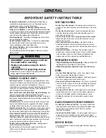
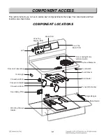
COMPONENT ACCESS
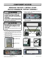
1. Turn off the electrical supply going to the range.
2. Pull the range away from the wall so that you can
access the rear panel.
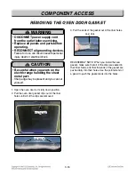
3. Remove the 3 screws from the rear control cover
and remove the cover.
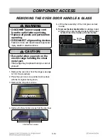
4. Remove the 17 screws from the rear back cover
and remove the cover.
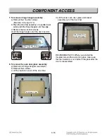
6. Remove 7 screws of KEY Membrane assembly and
separate PCB assembly.
7. Remove the 4 screws of the controller sub assembly
from the supporters.
8. Pull the controller sub assembly and lift it up from the
supporters.
9. For servicing the KEY Membrane, the controller sub
assembly should be separated in whole.
REMOVING THE BACK, CONTROL COVER
REMOVING THE BACK, CONTROL COVER
AND KEY MEMBRANE, SUPPOR
AND KEY MEMBRANE, SUPPOR
T ASSEMBL
T ASSEMBL
Y
Y
Control Cover
Back Cover
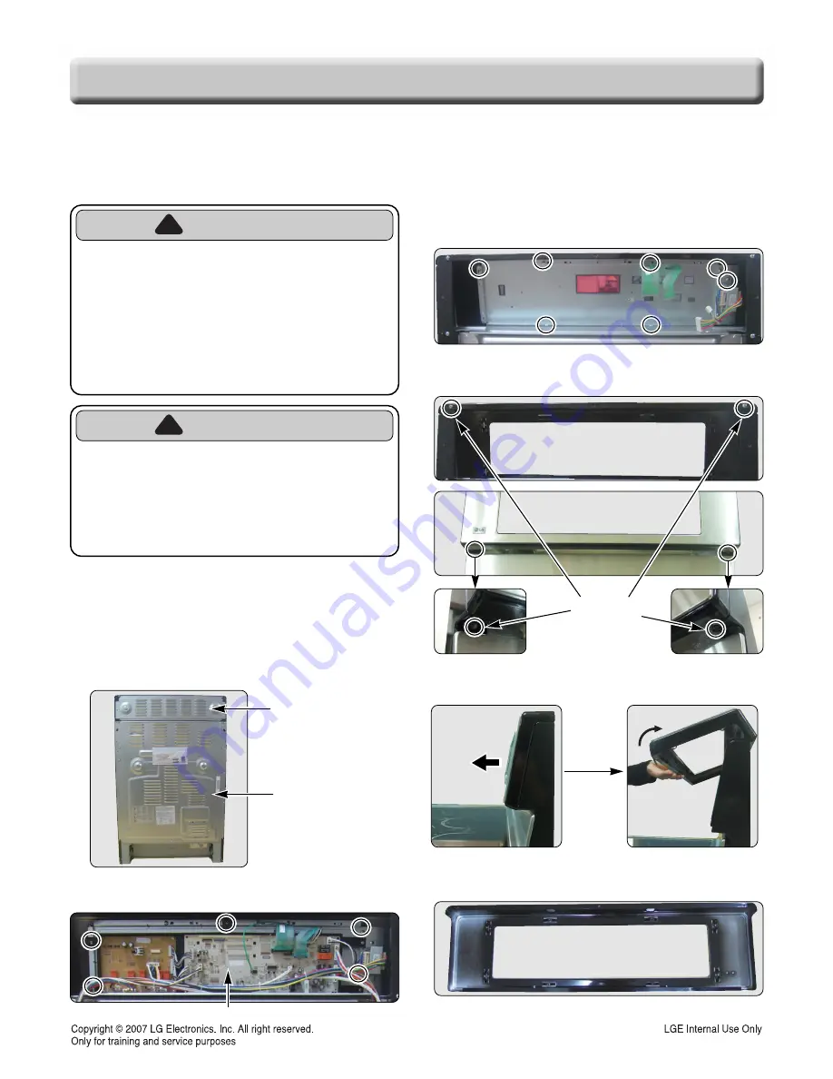
5. Remove the 5 screws of PCB assembly and separate
PCB assembly after unpluging the connectors.
PCB Assembly
4 Screws
Pull
Lift up
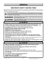
WARNING
• DISCONNET power supply cord
from the outlet before servicing.
• Replace all panels and parts before
operating.
• RECONNECT all grounding devices.
- Failure to do so can result in severe personal
injury, death or electrical shock.
!
CAUTION
• Be careful when you work on the
electric range handling the sheet
metal part.
- Sharp edge may be present and you can cut
yourself.
!
Содержание LRE30757SB
Страница 70: ...9 3 WARMNING DRAWER SELF CLEANING For Model LRE30757ST LRE30757SW LRE30757SB ...
Страница 71: ...9 4 CLOCK DISPLAY ON CR Warming Zone CONV BAKE CONV ROAST For Model LRE30757ST LRE30757SW LRE30757SB ...
Страница 73: ... 10 1 EXPLODED VIEW EV INTRODUCTION I DOOR PARTS DRAWER PARTS COOKTOP PARTS CONTROLLER PARTS CAVITY PARTS ...
Страница 79: ......


