

Precautions
•
Be sure to switch off the unit before
installation and connection.
•
The installation should be made by
qualified service personnel or system
installers.
•
Do not expose the power and
connection cables to moisture, which
may cause damage to the unit.
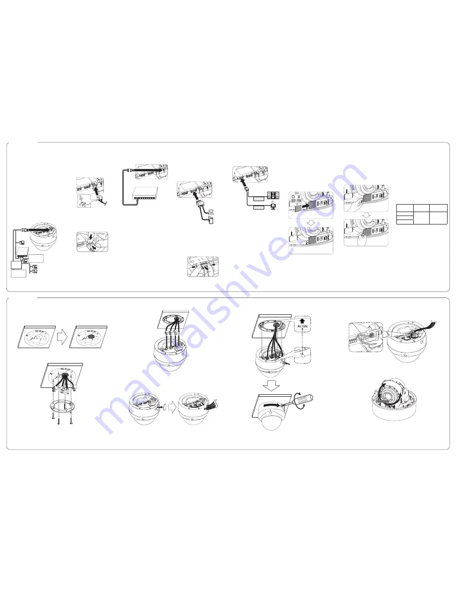
Connecting Network
You can control and monitor the system
via network. With the remote control
(monitoring), you can change the system
configuration or monitor the image via
network. After the installation, check the
network settings for the remote control and
monitoring work.
Connect the IP camera to your network using
a standard RJ-45 network cable as shown
below.
Broadband
Service
Broadband
Service
PoE Device
(IEEE802.3af)
Router
Connecting Power Source
Connect power, using one of the methods
listed below:
To use the power adapter
Connect a DC 12 V power source to the
power input terminal as shown below.
(recommended power adapter is DC 12 V /
1.5 A or above)
NOTE:
•
When the connecting Alarm and Audio,
tighten the screws as shown above.
•
Put your finger between the power
connector and the camera body to pull
out the connector.
To use the PoE (Power over Ethernet)
device
Connect the PoE cable to the LAN port on the
unit. You must use the “IEEE802.3af” standard
PoE device.
PoE Device
(IEEE802.3af )
NOTE:
If the camera doesn’t work properly after
connecting PoE device, please check if the
PoE device supplies enough power.
Connecting Alarm Device
Alarm terminals are used to connect the
alarm (relay) devices such as sensors, door
switches, etc.
ALARM IN & OUT / ALARM IN & OUT
RETURN (Sensor Input / Relay Output)
Connect the sensor device and alarm (relay)
device to the alarm terminal. Alarm signal is
outputted at an event occurrence.
AUDIO OUT
AUDIO IN
Alarm (relay)
Device
Sensor
Device
NOTE:
•
The Photo MOS Relay is rated for 100 mA
at DC 20 V or 100 mA at AC 28 V.
•
Grasp both ends of the 3 or 4 pin
connector plug and then sway both side
to pull it out.
Connecting Microphone
and Speaker Device
Optionally connect an active speaker and/or
external microphone with a built-in amplifier.
AUDIO OUT
AUDIO IN
NOTE:
Keep the microphone away from the speaker
to avoid howling.
Using the micro SD card
You can record your surveillance environment
with the micro SD card even if the network is
disconnected condition.
To insert the micro SD card
1. Remove the Dome Cover.
2. Insert the micro SD card carefully as
shown in the following illustrations.
Make sure the micro SD card terminal
position before insert the micro SD card.
Push the back end of the micro SD card
to fix it at the last step.
NOTE:
•
Do not use the power too much when
you insert the micro SD card. The micro
SD card may be damaged.
•
If you insert the micro SD card in the
wrong position, the micro SD card
may be damaged or it may cause the
malfunction of the micro SD Card Slot.
•
Keep the terminal part of the micro SD
card in clean. Be careful the terminal part
of the micro SD card not to dusty.
•
As the micro SD card is consumable, the
micro SD card end its days and may be
not able to save data if you use it more
than over certain times. In this case,
replace micro SD card to buy a new one.
R
emove the micro SD card
1. Press the back end of the micro SD card
to release the lock condition.
2. Take the micro SD card out carefully from
the camera. It may cause a malfunction
of the micro SD card or the micro SD
card slot if you use the power too much
at lock status.
CAUTION:
•
If you install the micro SD card on the
camera and remove with the micro SD
card condition indicator lights on, you
must unmount the micro SD card by
using the [System > Storage > Device
Management > Unmount] menu. The
micro SD card data is compromised or
the camera may not operate normally,
if you remove the card without use
[Unmount] function.
•
LG Electronics is not responsible for
deleted data caused by user mishandling
when you insert or remove the micro
SD card.
Recommended the micro SD card
specification
Maker
Capacity
Block Size
(FAT 32)
LG
Less than
32 GB
32 kbyte
Sandisk
Transcend
NOTE:
Speed of reading and writing more than
10 MB/Sec. (Class 6)
Connection
Mounting the camera
Follow the instructions below to surface mount the camera with supplied camera mounting
bracket.
1. Use the installation guide template to check the mounting location. Face the front of the
label toward the area of interest. Using the template as a guide, make a hole through the
ceiling.
2. Install the camera mounting bracket to the ceiling.
3. Connect the cables to the cable jacks of the camera body.
NOTE:
Push the cap from inside to arrange the cables through the conduit. (Optional)
4. Assemble the camera and the housing. Make sure when you assemble the camera in the
right direction. Lock the camera mounting bracket by tighten the fixing screw.
Fixing Screw
NOTE:
•
Adjust the position of [ALIGN] arrow, to the hole at the bottom of camera.
Then push and turn in the direction of the [LOCK] arrow.
•
Arrange the cables by cable tie after installation.
Camera Adjustment
Adjust the rotation position of the camera.
TILT
PAN
ROTATION
NOTE:
•
When you assemble the dome cover, make sure the SD card PCB position is aligned with the
LG logo.
•
The camera could be damaged by adjusting Pan, Tilt by force.
•
PAN: 350° / TILT: 67° / ROTATION: 355°
Installation


