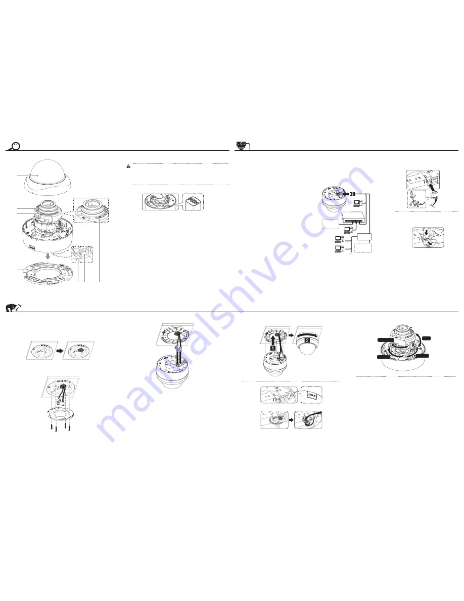
Part Names and Functions
a
c
b
d
e f
g
a
Dome Cover
b
IR LED
Do not stare at operating IR LED within hazard distances (1 m).
c
IR Sensor
d
Camera mounting bracket
You can lock the camera mounting bracket by tighten the screws.
To disassemble the camera from the mounting bracket, rotate the camera
counterclockwise with pressing the PUSH button inside the camera body.
,
e
Power input terminal
Connects to a DC 12 V power supply using proper cables. This camera must always be operated
a DC 12 V. Certified/Listed Adaptor which comply with LPS.
f
ETHERNET
Connects to a PC or a network via a hub with a 10 BASE-T/100 BASE-TX cable attached
RJ-45 connector.
g
RESET button
Push the button more than 3 seconds, this would restore the factory default network related
settings.
Installation
Mounting the camera
Follow the instructions below to surface mount the camera with supplied camera mounting
bracket.
1. Use the installation guide template to check the mounting location. Face the front of the label
toward the area of interest. Using the template as a guide, make a hole through the ceiling.
2. Disassemble the camera from the mounting bracket. Install the camera mounting bracket to
the ceiling.
3. Connect the cables to the cable jacks of the camera body.
4. Assemble the camera and mounting bracket after align the front part of the camera and
mounting bracket. Connect the unit by following step
a
and
b
.
•
Be careful of sharp edge after removing the cap of cable conduit.
•
Arrange the cables by cable tie after installation.
,
Camera Adjustment
Adjust the Pan/Tilt/Rotation position of the camera.
ROTATION
TILT
PAN 270°
PAN 90°
•
When you assemble the dome cover, make sure the arrow of base bracket position is
aligned with the LG logo.
•
Manual adjustment: PAN: 360° / TILT: 75° / ROTATION: 355°
•
When you adjust PAN/TILT/ROTATION manually, be careful your hand is not to hurt by
protrusions of other part.
•
When you adjust PAN/TILT/ROTATION manually, be careful the cable is not damaged or
pinched.
,
Connection
Precautions
•
Be sure to switch off the unit before installation and
connection.
•
The installation should be made by qualified service
personnel or system installers.
•
Do not expose the power and connection cables to moisture,
which may cause damage to the unit.
Connecting Network
You can control and monitor the system via network. With the
remote control (monitoring), you can change the system
configuration or monitor the image via network. After the
installation, check the network settings for the remote control
and monitoring work.
Connect the IP camera to your network using a standard RJ-45
network cable as shown below.
Broadband
Service
Broadband
Service
Ethernet device
(IEEE802.3af )
Router
Connecting Power Source
Connect a DC 12 V power source to the power input terminal as
shown below.
(Recommended power adapter is DC 12 V / 1.5 A or above)
•
When the connecting power adapter, tighten the
screws as shown above.
•
Put your finger between the power connector and the
camera body to pull out the connector.
,


