background image

Electrical Installation 

Danger 

•  Avoid  all  electrical  hazards  when  installing,  wiring, 

operating and maintaining all panels. 

•  Do  not  connect  panels  that  have  different  electrical 

properties  or  physical  configurations  in  the  same 
system. 

•  Match  the  polarities  of  cables  and  terminals  when 

making the connections; failure to do so may result  in 
damage to the panel. 

• The rating of the over-current device shall not exceed 

the  maximum  series  fuse  rating  marked  on  the  name 
plate. 

•  The  panel  contains  factory  installed  bypass  diodes 

located inside the  junction box. 

•  When  installing  the  system,  it  is  recommended  to 

install a lightning rod to protect the system. 

•  The  junction  box  should  not  be  opened.  Opening  the 

junction box will void the warranty. 

• Panels  with a suspected electrical problem should be 

returned to LG Electronics for inspection and possible 
repair or replacement per the limited warranty provided 
by LG Electronics  


Electrical Connections 

• Shock  hazard  may  occur  near  the  solar  modules 

electrical connections. 

•  Modules may be connected in series and/or parallel to 

achieve  the  desired  electrical  output  as  long  as  it  is 
within the guidelines on the product specification sheet.


•  Please  use  only  the  same  type  of  modules  in  a 

combined source circuit.


• Do not disconnect the module when it is operating.   
  Shock  hazard  may  occur  near  the  solar  modules 

connection means.  


Diodes 

• All  LG  modules  are  equipped  with  factory  installed 
bypass  diodes.  The  factory-installed  diodes  provide 
proper  circuit  protection  for  the  systems  within  the 
specified system voltage. 


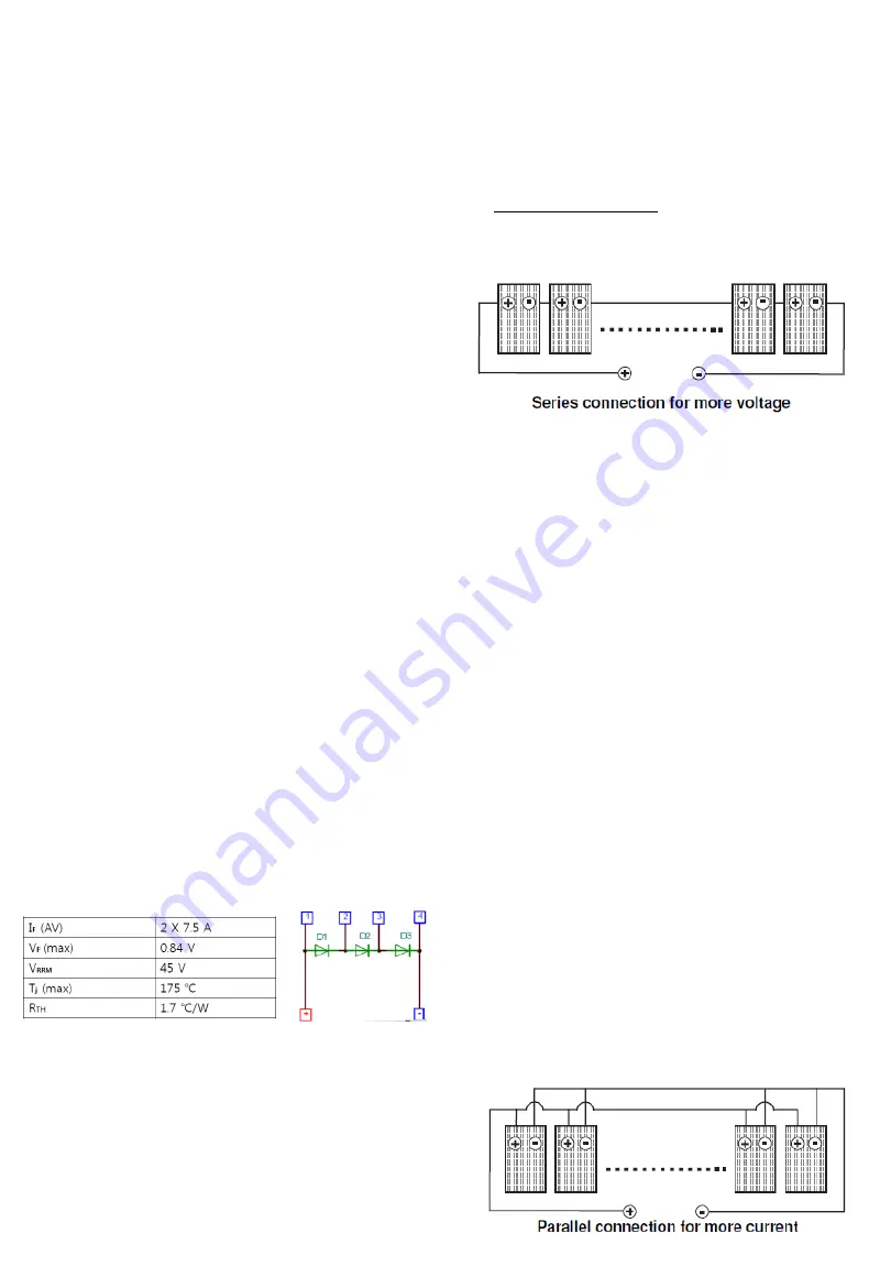
Series Connection


• The solar modules may be wired in series to produce 

the desired voltage output.  

• The current of each module connected in series should 

be the same.  

• The  maximum  number  of  series  connected 

modules can be determined by max system voltage, 
the 

125% 

safety 

factor 

not 

explained 

in 

specifications,  and  the  module  Voc  which  can  be 
checked  in 

“Product  Specifications”  in  this 

document.


 Do not exceed 80% 

of maximum system voltage.  

• Maximum Module configuration (recommend): refer 

to the 

„Product Specification‟ in this manual.


Parallel Connection 

• The  solar  modules  may  be  combined  in  parallel  to 
produce the desired current output. 
• When  modules  are  combined  in  parallel,  the  total 
current  is  equal  to  the  sum  of  currents  from  each 
module.  
• The  voltage  of  each  module  connected  in  parallel 
should be the same.  
• When  connecting  plural  strings  of  modules  in  parallel 
every  series  string  or  solar  module must  be fused  prior 
to combining with other strings.  
• Abide with all applicable federal, state, and local codes 
for additional fusing requirements and limitations on the 
maximum number of solar modules in parallel. 
• Maximum parallel strings without proper measures, e. 
g. fuse 15 A and/or blocking diode: 1 string. 
•  Parallel configuration is not limited if proper measures 
are taken to block the reverse current flow, e.g. fuses for 
the  protection  of  the  module  and  cables  from  over-
current  and/or  blocking  diodes  for  prevention  of 
unbalanced string voltage. 
• A multiplying factor is required for increased output of 
the PV modules. Under normal conditions, a PV module 
is  likely  to  experience  conditions  that  produce  more 
current  and/or  voltage  than  reported  at  standard  test 
conditions.  Accordingly,  the  values  of  Isc  and  Voc 
marked  on  this  PV  module  should  be  multiplied  by  a 
factor  of  125%  when  determining  component  voltage 
ratings,  conductor  ampacities,  fuse  sizes,  and  size  of 
controls to the PV output. 
• Follow  all  national,  state  and  local  codes  and 
standards applicable to overcurrent protection. 

Diode specification and configuration


Содержание LG S1C-G3 Series

Страница 1: ...Monocrystalline Solar Module LGXXXS1C W K G3 ...

Страница 2: ...1 Revisions Table Date Version Amendments Tech note 2012 08 01 1 0 1st edition Establish 2012 11 16 2 0 2nd edition Legality check ...

Страница 3: ...e frame or glass of the module may decrease the strength of the frame or break the glass Do not touch the glass surface or frame of the solar module after installation of the module It may result in injury or death Heavy objects must be kept off of the solar module Do not stand on or step on the module Do not drop the module Failure to comply may result in product damage product failure or bodily ...

Страница 4: ...ations are made at conditions of 1000W m2 irradiance and 25 C 77ºF solar cell temperature Colder temperatures may substantially increase voltage and power Keep the solar module and system away from children at all times Keep the module packed in the carton until the time of installation Keep flammable gasses away from the installation site Do not work alone Work as part of a team of two or more pe...

Страница 5: ...d in series should be the same The maximum number of series connected modules can be determined by max system voltage the 125 safety factor not explained in specifications and the module Voc which can be checked in Product Specifications in this document Do not exceed 80 of maximum system voltage Maximum Module configuration recommend refer to the Product Specification in this manual Parallel Conn...

Страница 6: ...e spring washer two flat washers one cup washer one star washer and 12 AWG Cu wires are recommended per mounting hole Where common grounding hardware nut bolts washers is used to attach a listed grounding device the attachment must be made in conformance with the grounding device manufacturer s instructions There is an earth hole on the edge of the module frame Using this hole an earth conductor a...

Страница 7: ... of 100mm When installed on a roof the solar module must be mounted over a fire resistant roof covering rated for the application The fire resistance of the solar module is class C after ANSI UL790 The solar module is only IEC listed for use when its factory frame is fully intact Removal or alteration must be done by an authorized and qualified individual Creating additional mounting holes may dam...

Страница 8: ...to the rooftop 2 Flat roof If installed with an additional stand such as wind shield or deflector Use four clamps on the long frame Use four mounting holes on two opposite sides Mounting Type Clamping Type Long Side Clamping Type Short Side LGXXXS1C W K G3 Clamping Range 230mm 270mm 270mm 7 Clamping Range From module Edge to 120mm Clamping Range From module Edge to 270mm Center 100mm Center 100mm ...

Страница 9: ... 600 12 MC4 1640 1000 35 16 8 15 LG250S1C G3 Yes 250 3 38 26 8 62 30 77 8 13 46 0 2 0 420 4 5 600 12 MC4 1640 1000 35 16 8 15 LG255S1C G3 Yes 255 3 38 41 8 72 30 97 8 24 46 0 2 0 420 4 5 600 12 MC4 1640 1000 35 16 8 15 LG260S1C G3 Yes 260 3 38 56 8 82 31 17 8 35 46 0 2 0 420 4 5 600 12 MC4 1640 1000 35 16 8 15 LG265S1C G3 Yes 265 3 38 71 8 92 31 37 8 46 46 0 2 0 420 4 5 600 12 MC4 1640 1000 35 16 ...

Страница 10: ... connected to installation operation or service of LG Solar Modules and if applicable from all liabilities claims demands losses or damages on my account caused or alleged to be caused in whole or in part by the negligence of the LG its affiliated companies successors or assigns its administrators directors agents officers volunteer and employees Disposal Please contact us if you have any queries ...

Страница 11: ...om http www lgsolarusa com This document is subject to change without notice LG LG logo and Life s Good are trademarks of LG Electronics Inc worldwide Trademarks and intellectual properties of LG Electronics Inc are protected by international copyright laws Document II G3 UL V2 EN 201211 10 ...

Отзывы: