51
171
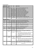
HRST#
Host reset input. The active-low input is referred to as hardware
reset and is used to reset this chip.
HD15~HD0
Host Data bus. This is the 8-bit or 16-bit bi-directioinal data bus to
the host. The lower 8 bits, HD0~HD7, are used for 8-bit data
transfers. Normally, data transfers are 16-bit wide.
Note : All pins except HD7 (no any pull) may be selectively pull-up
or pull-down with 40K resistant.
Default : 6mA, pull-up.
146
DMARQ
DMA request. This signal is used for DMA data transfers between
host and device and it shall be asserted by the MT1618 when it is
ready to transfer data to or from the host. The direction of data
transfer is controlled by DIOR# and DIOW#.
145
DIOW#
Device I/O write. Stop ultra DMA burst.
For Device I/O Write, this signal is the strobe signal asserted by
the host to write device register or the data port.
For Stop, Ultra DMA, this signal shall be negated by the host
before data is transferred in an Ultra DMA burst and is asserted
by host during an Ultra DMA burst to signal the termination of
Ultra DMA burst.
144
DIOR#
Device I/O read. Ultra DMA ready. Ultra DMA data strobe.
For Device I/O Read, this signal is the strobe signal asserted by
the host to read device registers or the data port.
For Ultra DMA Ready, this is asserted by the host to indicate to
the device that the host is ready to receive Ultra DMA data in
burst to the host.
For Ultra DMA data strobe, this signal is the data out strobe signal
from the host for an Ultra DMA data out burst.
143
IORDY
I/O Channel Ready. Ultra DMA ready. Ultra DMA data strobe.
For I/O channel Ready, this signal is negated to extend the host
transfer cycle of any register read or write when the device is not
able to complete the transfer.
For Ultra DMA Ready, this is asserted by the device to indicate to
the host that the device is ready to receive Ultra DMA data out
burst from the host.
For Ultra DMA data strobe, this is the data in strobe signal from
device for Ultra DMA data in burst to the host.
141
DMACK#
DMA Acknowledge. This signal shall be used by the host in
response to DMARQ to acknowledge that it is ready for DMA
transfers.
140
INTRQ
Device Interrupt. This signal is used to interrrupt the host system.
INTRQ is driven only when this chip is addressed. When not
driven, INTRQ is in a high impedance state.
138
IOCS16#
Device 16-BIT I/O. In PIO transfer modes 0, 1, and 2, IOCS16#
indicates to the host system that the 16-bit data port has been
addressed and that the device is prepared to send or receive a
16-bit data word.
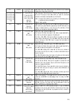
3.3V LVTTL Input,
SMT,75K pull-up
3.3V LVTTL I/O
Slew rate, SMT,
2mA, 4mA, 6mA,
8mA, 10mA PDR,
40K PPU,
40K PPD
3.3V LVTTL I/O,
Slew rate,
10mA driving
3.3V LVTTL Input,
SMT,
40K pull-up
3.3V LVTTL Input,
SMT,
40K pull-up
3.3V LVTTL I/O,
Slew rate,
10mA driving
3.3V LVTTL Input,
SMT,
40K pull-up
3.3V LVTTL I/O,
Slew rate,
10mA driving, SMT
3.3V LVTTL output,
Slew rate,
10mA driving,
(open-drain)
147, 149, 151,
153, 156, 159,
161, 166, 167,
164, 160, 158,
155, 152, 150,
148


