


Copyright
2007 LG Electronics. Inc. All right reserved.
Only for training and service purposes
LGE Internal Use Only
- 13 -
220
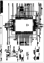
IBM
Compatible PC
PARALLEL PORT
Power inlet (required)
Power LED
ST Switch
Power Select Switch
(110V/220V)
Control Line
Not used
RS232C
PARALLEL
V-SYNC
POWER
ST
VGS
MONITOR
E
E
V-Sync On/Off Switch
(Switch must be ON.)
F
F
A
A
B
B
C
C
15
10
5
5
6
9
1
1
1
14
13
25
6
5V
5V
5V
4.7K
4.7K
4.7K
74LS06
74LS06
OFF
ON
OFF
ON
11
Video Signal
Generator
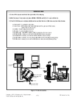
Figure 1. Cable Connection
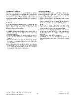
SERVICE OSD
1) Turn off the power switch at the right side of the display.
2) Wait for about 5 seconds and press MENU, POWER switch for 1 second interval.
3) The SVC OSD menu contains additional menus that the User OSD menu as described below.
a) CLEAR ETI : To initialize using time.
c) Auto Color : W/B balance and Automatically sets the gain and offset value.
(press key for over 3 sec)
d) AGING : Select Aging mode(on/off).
b) Module : To select applied module.
d) NVRAM INIT : EEPROM initialize.(24C16, press key for over 3 sec)
e) R/G/B-9300K : Allows you to set the R/G/B-9300K value manually.
f) R/G/B-6500K : Allows you to set the R/G/B-6500K value manually.
g) R/G/B-Offset : Allows you to set the R/G/B-Offset value manually.(Analog Only)
h) R/G/B-Gain : Allows you to set the R/G/B-Gain value manually.(Analog Only)
Содержание FLATRON W2241S
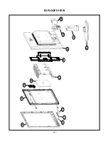
Страница 19: ...EXPLODED VIEW 300 320 310 410 400 430 910 920 440 200 330 450 460 19 420 ...
Страница 21: ......
Страница 22: ......
Страница 23: ......
Страница 24: ......
Страница 25: ...MAY 2008 P NO MFL32179265 Printed in China ...


