background image

- 9 -

5. AD9883A-Set Adjustment

5-1 Synopsis

AD9883A-Set adjustment to set the black level and the Gain
of optimum with an automatic movement from the analog =>
digital converter and RGB revises a deviation a function for it
is.

5-2 Test Equipment 

R/C for adjustment, 801GF(802B, 802F, 802R) Pattern
Generator
(720P  The Vertical 100% Color Bar Pattern output will be
possible and the output level will accurately have to be
revised with 0.7±0.1Vp-p)

5-3 Adjustment

(1) Input the 100% Vertical Color Bar Pattern(TVBAR_100) of

720P Mode possible Component input support, select the
Component1 or Component2 an input selection and select
the Clear image.  

(2) After signal receiving above 1 second, press the ADJ Key

on R/C for adjustment enter the ‘Ez - Adjust’ and select the
‘5. AD9883A-Set’.
Pressing the + Key adjust with automatic movement. 

(3) When the adjustment is over in the normality and the

message which is a ‘AD9883 - Set’ becomes the display
and the case which has not become the normality the
message which is a ‘AD9883A set error’ becomes the
display.

(4) Readjust after confirming the case Pattern or adjustment

condition where the adjustment had not become the
normality. 

(5) After adjustment complete, exit the adjustment mode by

press ADJ KEY. 

6. Adjustment of White Balance

6-1. Required Equipment

(1) Color analyzer (CA-100 or same product)
(2) Automatic adjustor (with automatic adjustment hour

necessity and the RS-232C communication being possible)

(3) AV Pattern Generator

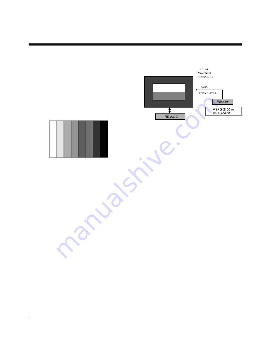
6-2. Connection Diagram of Equipment for 

Measuring 

(Automatic Adjustment)

6-3. Adjustment of White Balance

O

Operate the Zero-calibration of the CA-100, then stick sensor
to PDP module surface when you adjust.

O

For manual adjustment, it is also possible by the following

sequence. 

(1) Enter the ‘Ez - Adjust’ by pressing ADJ KEY on R/C for

adjustment.

(2) Select the 3. WHITE PATTERN using CH +/- Key and HEAT

RUN above 15 minutes by pressing the ENTER Key.

(3) Receive the Window pattern signal from AV Pattern

Generator. (AV Input)

(4) Set Picture condition to “CLEAR Image”.
(5) After stick sensor to center of screen, select the ‘2. White-

Balance’ of ‘Ez - Adjust’ by pressing the ADJ KEY n R/C for
adjustment. And enter adjustment mode by pressing the Right
KEY(

G

) .

(6) Adjust the Hight Light using R Gain/B Gain and adjust the

Low Light using G Cut/B Cut.

(7) Adjust using /- KEY.

(G Gain : 120 / R Cut : 63)

Hight Light : 150±10 Cd
Low Light   : 5±2 Cd

X; 0.280±0.003
Y; 0.290±0.003

Color temperature: 10,000°K±500°K

(8) After adjustment complete, move to Ez - Adjust screen by

pressing the ENTER(

Y

) KEY. And exit the adjustment mode

by press ADJ KEY.

ADJUSTMENT INSTRUCTIONS

<Fig 3>  Adjustment Pattern : 720P Vertical Color Bar

High Light Adjustment

Low Light Adjustment

Signal Input

<Fig 4>  Connection Diagram of Automatic Adjustment

Содержание DU-50PZ60H

Страница 1: ... TV SERVICE MANUAL CAUTION BEFORE SERVICING THE CHASSIS READ THE SAFETY PRECAUTIONS IN THIS MANUAL CHASSIS AF 03BA MODEL DU 50PZ60 H website http biz LGservice com e mail http www LGEservice com techsup html ...

Страница 2: ... With the instrument AC plug removed from AC source connect an electrical jumper across the two AC plug prongs Place the AC switch in the on positioin connect one lead of ohm meter to the AC plug prongs tied together and touch other ohm meter lead in turn to each exposed metallic parts such as antenna terminals phone jacks etc If the exposed metallic part has a return path to the chassis the measu...

Страница 3: ...PTION OF CONTROLS 4 SPECIFICATIONS 7 ADJUSTMENT INSTRUCTION 8 PRINTED CIRCUIT BOARD 11 BLOCK DIAGRAM 17 EXPLODED VIEW 18 EXPLODED VIEW PARTS LIST 19 REPLACEMENT PARTS LIST 20 SCHEMATIC DIAGRAM TABLE OF CONTENTS ...

Страница 4: ...onnects the video signal from a video device AUDIO Input Use to connect to hear stereo sound from an external device TV VIDEO Button VOLUME F F G G Buttons Power Standby Indicator Illuminates red in standby mode Illuminates green when the TV is turned on This is a simplified representation of front panel Here shown may be somewhat different from your TV Remote Control Sensor CHANNEL E E D D Button...

Страница 5: ...ce Component1 Input Digital Audio Output Connect digital audio from various types of equipment Note In standby mode these ports will not work Audio Video Input 1 Connect audio video output from an external device to these jacks DVD DTV Input Component 1 2 Connect a component video audio device to these jacks Monitor Output Connect a second TV or Monitor Remote Control Port Connect your wired remot...

Страница 6: ...atically SURF Use to scroll the Surf channel list CC Select a closed caption Off EZ Mute and On FLASHBK Tunes to the last channel viewed THUMBSTICK Up Down Left Right OK Allows you to navigate the on screen menus and adjust the system settings to your preference CHANNEL UP DOWN Selects available channels found with EZ scan EXIT Clears all on screen displays and returns to TV viewing from any menu ...

Страница 7: ... 3 85 98 101 2 45 9 48 3 1226 2 30 6 778 3 9 99 98 1 44 5 Width inches mm Height inches mm Depth inches mm Weight pounds kg Power requirement Television System Program Coverage External Antenna Impedance Resolution Color Operating Temperature Range Operating Humidity Range DU 42PZ60 42PZ60A 42PZ60B 42PZ60C 42PZ60H 42PZ60K 42PZ60R 42PZ60S DU 50PZ60 50PZ60A 50PZ60B 50PZ60C 50PZ60H 50PZ60K 50PZ60R 50...

Страница 8: ...nutes Especially Digital pattern 13 CH Cross Hatch Pattern a afterimage may be occur in the black level part of the screen 3 EPLD Download 1 Test Equipment Jig for PC download 2 Connect the power of VSC B D 3 Execute download program Flash Loader of PC 4 After executing execution hot key Programmer icon click 5 End after confirming Each PCB Assy must be checked by Check JIG Set before assembly Esp...

Страница 9: ...uired Equipment 1 Color analyzer CA 100 or same product 2 Automatic adjustor with automatic adjustment hour necessity and the RS 232C communication being possible 3 AV Pattern Generator 6 2 Connection Diagram of Equipment for Measuring Automatic Adjustment 6 3 Adjustment of White Balance O Operate the Zero calibration of the CA 100 then stick sensor to PDP module surface when you adjust O For manu...

Страница 10: ...sing the Right KEY G 2 When enter adjustment mode becomes the image TV 6CH SPLIT Screen with automatic movement and appear below window 3 The contour of US 6CH letter of left Main screen is most clear and it is clear 1 Contrast Main after adjusting first in order for right side Sub screen to contrast to become the left Main screen to contrast with same 2 Contrast Sub it adjust This time adjust usi...

Страница 11: ... 11 PRINTED CIRCUIT BOARD MAIN TOP ...

Страница 12: ... 12 PRINTED CIRCUIT BOARD MAIN BOTTOM ...

Страница 13: ... 13 PRINTED CIRCUIT BOARD TUNER TOP ...

Страница 14: ... 14 PRINTED CIRCUIT BOARD TUNER BOTTOM ...

Страница 15: ... 15 PRINTED CIRCUIT BOARD REAR AV TOP REAR AV BOTTOM FRONT AV TOP FRONT AV BOTTOM POWER S W ...

Страница 16: ... 16 SPK TOP SPK BOTTOM CONTROL TOP CONTROL BOTTOM PRINTED CIRCUIT BOARD ...

Страница 17: ... 17 BLOCK DIAGRAM ...

Страница 18: ... 18 EXPLODED VIEW 301 303 302 300 305 400 205 212 201 203 200 213 202 210 208 209 207 206 211 580 304 581 410 430 102 101 440 420 570 540 550 551 552 401 530 531 590 532 520 524 521 523 525 522 103 ...

Страница 19: ...ILTER AL DN 50PZ60 SIDE 304 4980V00374A SUPPORTER MODULE EGI CENTER MN 50PZ40 305 3790V00683C FILTER MECH MN 50PZ41 1150G03EK NBK 50 MESH SINGLE GLASS FILTER 400 3809V00B03A BACK COVER ASSEMBLY DN 50PZ60 NON NON 401 3301V00014B PLATE ASSEMBLY A V 3300V00244 DU 50PZ60 410 4980V00790A SUPPORTER MODULE AL DIE CASTING DN 50PZ60 SUPP_MODULE ASSY 420 4980V00790B SUPPORTER MODULE AL DIE CASTING DN 50PZ60...

Страница 20: ...C107 IC108 IC200 IC201 IC202 IC203 IC210 IC211 IC305 IC306 IC308 IC310 IC400 IC401 IC402 IC403 IC404 IC500 IC501 IC600 IC601 IC602 IC603 IC701 IC702 IC703 IC704 IC705 IC706 IC707 IC801 0IMCRSS016A 0IMMRAL016A 0IAL242110A 0IMCRRH001A 0IMMRAL016A 0IMCRSJ001A 0IAL242110A 0IMMRSS041C 0IMCRSH001A 0IMMRSS041C 0ITK118100B 0IKE702900G 0ITK118100B 0ICTMLG014A 0IPH741400E 0ISA428200A 0IMCRSH001A 0IAL242561B...

Страница 21: ...KEC CHIP 2SC3875S ALY KEC CHIP 2SC3875S ALY KEC CHIP 2SC3875S ALY KEC CHIP 2SC3875S ALY KEC KRA102S R TP KEC SOT23 CHIP TR CHIP 2SC3875S ALY KEC CHIP KDS226 SOT23 LOCA NO PART NO DESCRIPTION D101 D102 D103 D105 D106 D107 D114 D701 D803 D901 D906 D907 DL700 DL702 DL703 DL704 LD001 LD801 ZD101 ZD102 ZD801 ZD802 ZD902 ZD903 ZD904 ZD905 ZD906 ZD907 ZD908 ZD909 C002 C101 C102 C102 C103 C104 C105 C106 C...

Страница 22: ... 16V 20 22UF MV 16V 20 220UF STD 50V M 0 1UF D 100V 10 220UF MV 16V 20 220UF MV 16V 20 220UF STD 50V M LOCA NO PART NO DESCRIPTION C1915 C1916 C1917 C1918 C1919 C192 C1921 C1924 C1929 C193 C1930 C195 C197 C199 C200 C201 C206 C229 C230 C244 C249 C303 C310 C311 C313 C317 C322 C323 C325 C330 C331 C332 C333 C335 C343 C349 C350 C352 C353 C379 C380 C503 C505 C520 C529 C540 C541 C545 C545 C548 C605 0CE47...

Страница 23: ...0 22UF MV 16V 20 22UF MV 16V 20 1UF MV 50V 20 470UF MV 16V 20 10UF MV 16V 20 220UF MV 16V 20 10UF MV 16V 20 1UF MV 50V 20 220UF MV 16V 20 LOCA NO PART NO DESCRIPTION C906 C908 C917 C919 C921 C927 C930 C936 C938 C940 C941 C949 C950 C952 C953 C954 C957 C966 C967 C968 C970 C981 C986 C987 JK101 JK102 JK103 JK104 JK104 JK105 JK106 JK106 JK107 JK108 JK109 JK110 JK112 JK113 L120 L121 L701 L703 L705 L706 ...

Страница 24: ...2 L303 L304 L305 L306 L400 L500 L501 L503 L504 L509 L510 L511 L513 L600 L702 L704 L801 L802 L803 L805 L809 L815 L816 L909 L910 L914 L915 L916 L917 L918 L919 L920 L921 LT801 LT802 LT803 6210VC0006A 6210VC0006A 6210VC0006A 6210VC0006A 6210VC0006A 6210VC0006A 6210VC0006A 6210VC0006A 6210VC0006A 6210VC0006A 6210VC0006A 6210VC0006A 6210VC0006A 6210VC0006A 6210VC0006A 6210VC0006A 6210VC0006A 6210VC0006A...

Страница 25: ...000LN2 FILTER EMC MLB2012091000LN2 FILTER EMC MLB2012091000LN2 FILTER EMC BK2125 HS 750 FILTER EMC BK2125 HS 750 RESONATOR CRYSTAL HC49 SM 10 0MHZ RESONATOR CRYSTAL SX1SMD 20250000HZ RESONATOR CRYSTAL SX1SMD 20250000HZ RESONATOR CRYSTAL HC49 SM4H 4MHZ RESONATOR CRYSTAL HC49 SM5H 20MHZ RESONATOR CRYSTAL SX1SMD 8 0MHZ RESONATOR CRYSTAL SX1 18 432000MHZ CONNECTOR DSUB 15PIN 2 29MM CONNECTOR DSUB 24P ...

Страница 26: ......

Страница 27: ...Dec 2003 Printed in Korea P NO 3828VD0147B ...

Страница 28: ......

Страница 29: ......

Страница 30: ......

Страница 31: ......

Отзывы: