background image

Standard Repair Process Detail Technical Manual 

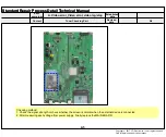
Wifi operation checking method 

 A24 

Established  

date  

Revised  

date  

Error 

symptom 

Content 

 TV 

A14 

D. Function error 

Standard Repair Process Detail Technical Manual 

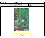
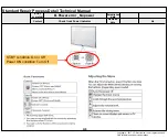
Motion  Remote operation checking method 

Established  

date  

Revised  

date  

Error 

symptom 

Content 

 TV 

 A23 

D. Function error 

Standard Repair Process Detail Technical Manual 

Motion  Remote operation checking method 

D. Function error 

 A14 

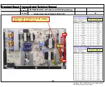
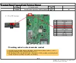
 Checking order 
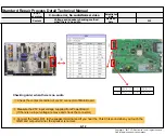
1.Check BT/Wifi cable condition between BT/Wifi assy & Main board.

2.Check the 3.5V on the terminal  6

① Wifi & BT Front

 Wifi & BT Rear 


Pin 

Pin name 

GND 

BT_RESET 

N.C 

WOL/WIFI_POWER_ON 

GND 

WIFI_DP 

WIFI_DM 

+3.5V_WIFI 

Established 

date 

Revised 

date 

Error 

symptom 

Content 

Error 

symptom 

Content 

Copyright ©  2017  LG Electronics. Inc. All rights reserved. 

Only for training and service purposes.

Содержание 55EG9A7V

Страница 1: ...ED79A MODEL 55EG9A7V 55EG9A7V ZB CAUTION BEFORE SERVICING THE CHASSIS READ THE SAFETY PRECAUTIONS IN THIS MANUAL OLED TV SERVICE MANUAL CONFIDENTIAL Copyright 2017 LG Electronics Inc All rights reserved Only training and service purposes ...

Страница 2: ...ghts reserved Only for training and service purposes CONTENTS CONTENTS 2 SAFETY PRECAUTIONS 3 SERVICING PRECAUTIONS 4 SPECIFICATION 6 SOFTWARE UPDATE 13 BLOCK DIAGRAM 14 EXPLODED VIEW 20 DISASSEMBLY GUIDE 21 TROUBLE SHOOTING GUIDE APPENDIX ...

Страница 3: ...he set is safe to operate without damage of electrical shock Leakage Current Cold Check Antenna Cold Check With the instrument AC plug removed from AC source connect an electrical jumper across the two AC plug prongs Place the AC switch in the on position connect one lead of ohm meter to the AC plug prongs tied together and touch other ohm meter lead in turn to each exposed metallic parts such as ...

Страница 4: ...charge on your body by touching a known earth ground Alter natively obtain and wear a commercially available discharg ing wrist strap device which should be removed to prevent potential shock reasons prior to applying power to the unit under test 2 After removing an electrical assembly equipped with ES devices place the assembly on a conductive surface such as aluminum foil to prevent electrostati...

Страница 5: ...oints of the two original leads If they are not shiny reheat them and if necessary apply additional solder Fuse and Conventional Resistor Removal Replacement 1 Clip each fuse or resistor lead at top of the circuit board hollow stake 2 Securely crimp the leads of replacement component around notch at stake top 3 Solder the connections CAUTION Maintain original spacing between the replaced component...

Страница 6: ...d Latvia Estonia Lithuania Poland Portugal Romania Albania Bosnia Slovakia Beralus DTV MPEG2 4 DVB T2 11 countries UK Ireland Sweden Denmark Finland Norway Ukraine Kazakhstan Russia Italy Croatia Serbia DTV MPEG2 4 DVB C 37 countries Germany Netherland Switzerland Hungary Austria Slovenia Bulgaria France Spain Italy Belgium Russia Luxemburg Greece Czech Croatia Turkey Moroco Ireland Latvia Estonia...

Страница 7: ...it s 1 4 1 8 1 16 1 32 Modulation Code Rate QPSK 1 2 2 3 3 4 5 6 7 8 16 QAM 1 2 2 3 3 4 5 6 7 8 64 QAM 1 2 2 3 3 4 5 6 7 8 DVB T2 Guard Interval Bitrate_Mbit s 1 4 1 8 1 16 1 32 1 128 19 128 19 256 Modulation Code Rate QPSK 1 2 2 5 2 3 3 4 5 6 16 QAM 1 2 2 5 2 3 3 4 5 6 64 QAM 1 2 2 5 2 3 3 4 5 6 256 QAM 1 2 2 5 2 3 3 4 5 6 DVB C Symbolrate 4 0Msymbols s to 7 2Msymbols s Modulation 16QAM 64 QAM 12...

Страница 8: ...080P 5 1 2 HDMI Input DTV No Resolution H freq kHz V freq Hz Pixel clock MHz Proposed Remarks 1 640 480 31 46 59 94 25 13 SDTV 480P 2 640 480 31 50 60 00 25 13 SDTV 480P 3 720 480 15 73 59 94 13 50 SDTV DVD 480I 525I Spec out but display 4 720 480 15 75 60 00 13 51 SDTV DVD 480I 525I 5 720 576 15 62 50 00 13 50 SDTV DVD 576I 625I 50Hz 6 720 480 31 47 59 94 27 00 SDTV 480P 7 720 480 31 50 60 00 27 ...

Страница 9: ...Hz V freq Hz Pixel clock VIC 3D input proposed mode Proposed 1 640 480 31 46 31 50 59 94 60 00 25 13 25 20 1 Top and Bottom Side by side half Secondary SDTV 480P Secondary SDTV 480P 31 46 31 50 59 94 60 00 50 35 50 40 1 Side by side Full SDTV 480P 62 93 63 00 59 94 60 00 50 35 50 40 1 Frame packing Line alternative Secondary SDTV 480P SDTV 480P 2 720 480 31 46 31 50 59 94 60 00 27 00 27 03 2 3 Top...

Страница 10: ...V 1080I 56 25 50 00 148 50 20 Frame packing Field alternative Primary HDTV 1080I HDTV 1080I 67 43 67 50 59 94 60 00 148 35 148 50 5 Frame packing Field alternative Primary HDTV 1080I HDTV 1080I 7 1920 1080 26 97 27 00 23 97 24 00 74 17 74 25 32 Top and Bottom Side by side half Primary HDTV 1080P Primary HDTV 1080P 26 97 27 00 23 97 24 00 148 35 148 50 32 Side by side Full HDTV 1080P 28 12 25 00 74...

Страница 11: ...35 HDTV 1080P 2D to 3D Side by Side half Top Bottom 9 1920 1080 27 00 24 00 74 25 HDTV 1080P 2D to 3D Side by Side half Top Bottom 10 1920 1080 28 12 25 00 74 25 HDTV 1080P 2D to 3D Side by Side half Top Bottom 11 1920 1080 56 25 50 00 74 25 HDTV 1080P 2D to 3D Side by Side half Top Bottom 12 1920 1080 26 97 23 97 74 18 HDTV 1080P 2D to 3D Side by Side half Top Bottom 13 1920 1080 33 75 30 00 74 2...

Страница 12: ...00 SDTV 576P 3 1280 720 45 00 60 00 74 25 HDTV 720P 37 50 50 00 74 25 HDTV 720P 4 1920 1080 33 75 60 00 74 25 HDTV 1080I 2D to 3D Side by Side Half Top Bottom 28 12 50 00 74 25 HDTV 1080I 5 1920 1080 27 00 24 00 74 25 HDTV 1080P 2D to 3D Side by Side Half Top Bottom Checker Board Row Interleaving Column Interleaving 28 12 25 00 74 25 HDTV 1080P 33 75 30 00 74 25 HDTV 1080P 67 50 60 00 148 50 HDTV ...

Страница 13: ...ow move to About This TV page for update 5 TV is updating 6 After finished the update below Pop up appear 7 Click Yes TV will be DC OFF ON 8 After TV turned on Check the updated SW Version and Tool Option 2 NSU 1 Menu All Settings General About This TV 2 Click CHEK FOR UPDATES system check newest version 3 Click DOWNLOAD AND INSTALL 4 TV is updating 5 After finished the update below Pop up appear ...

Страница 14: ...HDMI1 1 4 HDMI2 1 4 HDMI3 1 4 SYSTEM EEPROM 256Kb USB2 2 0 USB3 2 0 eMMC 4GB Sub Micom DDR3 2133 X 16 128MB X 2EA P_TS X_TAL 24MHz I2S Out AV D Demod I2C 4 R E A R S I D E R E A R H SPDIF OUT BLUTOOTH IR KEY EYE WIFI SUB ASSY IR KEY Tuner I2C 6 X_TAL 25MHz I2C CVBS SIF Tuner COMP ARC X_TAL 32 768kHz OCP 1 5A OCP 1 5A USB1 2 0 OCP 1 5A Demod ATSC DVB T C ISDB T Analog Demod ...

Страница 15: ...31 TP_DVB_DATA0 AJ30 TP_DVB_DATA1 AK31 TP_DVB_DATA2 AK33 TP_DVB_DATA3 AK32 TP_DVB_DATA4 AL33 TP_DVB_DATA5 AL32 TP_DVB_DATA6 AM33 TP_DVB_DATA7 3 3V_TUNER 3 3Kȳ 33 ȳ TPO_DATA 0 7 CI_IN_TS_DATA 0 7 CI Slot No use 100 ȳ TPI_DATA 0 7 CI_TS_DATA 0 7 PCM_WE PCM_OE PCM_IRQA PCM_REG PCM_INPACK PCM_WAIT PCM_RESET CI_DATA 0 7 CI_ADDR 0 14 PCM_IORD PCM_IOWR PCM_CE1 CI_TS_VAL CI_CD1 2 CI 5V Power detect PCM_5V...

Страница 16: ...AK24 PR2_IN COMP1_Pb COMP1_Pr COMP2_Y COMP2_Y_IN_SOC_SOY COMP2_Y_IN_SOC COMP2_PB_IN_SOC COMP2_PR_IN_SOC JACK AV A A 1 ACK Jack Side SOC Side SPDIF_OUT SPDIF OUT AM15 IEC958OUT SPDIF_OUT_ARC AE28 HDMI_1_ARC COMP1 AV1 DVI_R_IN COMP1 AV1 DVI_L_IN AN17 AUAD_L_CH3_IN AM17 AUAD_R_CH3_IN AUAD_R_CH3_IN AUAD_L_CH3_IN ARC OUT HDMI3 Speaker MICOM AMP_RESET_N DAC_LRCH DAC_SCK DAC_LRCK I2C_SCL_1 I2C_SDA_1 I2S ...

Страница 17: ... 1 4 _V CEC_REMOTE Port_2 DDC_SCL_2 DDC_SDA_2 HDMI_HPD_2 CEC_REMOTE Port_1 DDC_SCL_4 DDC_SDA_4 HDMI_HPD_4 HDCP1 4 HDCP2 2 5V 5V HDCP1 4 HDCP2 2 HDMI 3 1 4 _H ARC CEC_REMOTE Port_3 DDC_SCL_1 DDC_SDA_1 SPDIF_OUT_ARC HDMI_HPD_1 HDMI_HPD_4 HDMI_4_SCL HDMI_4_SDA HDMI_2_HPD HDMI_2_SDA HDMI_2_SCL HDMI_1_HPD HDMI_1_SCL HDMI_1_SDA HDMI_1_ARC 5V MAIN SOC ...

Страница 18: ... RS232 IC WIFI_DP DM MICOM WOL WIFI_POWER_ON USB2_0_DP0 DM0 SOC_RX TX USB3_DP1 DM1 USB_DP2 DM2 USB_DP1 DM1 USB3_DP0 DM0 JK6800 RS232C phone Jack SOC_RX TX UART wafer SOC_RX TX USB 1 2 0 _V USB 2 2 0 _V USB 3 2 0 _H WIFI_EN 3 5V_WIFI OCP USB_CTL3 5V_USB_1 OCP EB_CS2 USB_CTL2 5V_USB_2 OCP HUB_VBUS_CTRL0 USB_CTL1 5V_USB_3 UART0_TXD MAIN SOC USB2_1_DP0 DM0 EB_CS0 ...

Страница 19: ... MAIN SOC MICOM ZZ LNB No use IR KEY EYE XWW ZUZr EYE_SDA EYE_SCL 3 5V_ST 18pF Cap Ready I2C_SCL5 AH10 SCL4 I2C_SDA5 AJ10 SDA4 I2C_SCL_MICOM_SOC AH9 SCL1 I2C_SDA_MICOM_SOC AG9 SDA1 I2C_SCL4 AH22 SCL3 I2C_SDA4 AJ22 SDA3 I2C_SCL1 AH11 SCL0 I2C_SDA1 AG11 SDA0 I2C_SCL2 AG10 SCL2 I2C_SDA2 AJ9 SDA2 I2C_SCL6 AG23 SCL5 I2C_SDA6 AH24 SDA5 Tuner ZUZr 3 3V_TU ZZ 47pF 3 3V_NORMAL ZUZr T CON L DIMING 33pF XWWG...

Страница 20: ...ical and mechanical parts in this chassis have special safety related characteristics These parts are identified by in the EXPLODED VIEW It is essential that these special safety parts should be replaced with the same components as recommended in this manual to prevent Shock Fire or other Hazards Do not modify the original design without permission of manufacturer IMPORTANT SAFETY NOTICE ...

Страница 21: ...Copyright LG Electronics Inc All rights reserved Only for training and service purposes 2 Remove Rear Small Cover Pull up bottom of Rear Small Cover to remove DISASSEMBLY GUIDE 1 Put the set on the flat pad ...

Страница 22: ...4 Remove Back Cover Screw FAB31843216 M3 5 5mm Gray 9EA j G G ˉV ˉ G 5 Remove PowerCord Bracket FAB31843216 M3 5 5mm Gray 1EA h G G ˉ Pull up Power Cord than remove Bracket next remove cord from PSU 3 Remove Stand Screw and Stand FAB30016103 M4 12mm 4EA Remove Screw 4EA first next remove Stand ...

Страница 23: ... 23 Copyright LG Electronics Inc All rights reserved Only for training and service purposes 6 Remove Back Cover Pull up bottom of Back Cover to remove ...

Страница 24: ...TROUBLE SHOOTING GUIDE Copyright 2017 LG Electronics Inc All rights reserved Only for training and service purposes ...

Страница 25: ... off while viewing power auto on off 7 8 C Audio error No audio Normal video 8 9 Wrecked audio discontinuation noise 9 10 D Function error Remote control Local switch checking 10 MR15RA operating checking 11 11 12 Wifi operating checking 12 13 External device recognition error 13 14 E Noise Circuit noise mechanical noise 14 15 F Exterior error Exterior defect 15 First of all Check whether there is...

Страница 26: ...ways check record S W Version and White Balance value before replacing the Main Board Replace Main Board Re enter White Balance value Precaution Established date Standard Repair Process Revised date 1 15 Error symptom A Video error No video Normal audio A9 A9 A4 A2 First of all Check whether all of cables between board is inserted properly or not Main B D Power B D Vx1 Cable Speaker Cable IR B D C...

Страница 27: ...audio Check and replace MAIN B D Y Replace Power Board and repair parts N End Standard Repair Process A Video error No video No audio A9 Established date Revised date 2 15 Error symptom 2 Copyright 2017 LG Electronics Inc All rights reserved Only for training and service purposes ...

Страница 28: ...g By using Digital signal level meter By using Diagnostics menu on OSD All Settings Channels Channel Tuning Manual Tuning Check the Signal Signal strength Normal over 50 Signal Quality Normal over 50 Normal Picture Y Contact with signal distributor or broadcaster Cable or Air N Normal Picture Y Close N A4 Standard Repair Process Established date Revised date 3 15 Error symptom 3 N Y Close N S W Up...

Страница 29: ...ck external device and cable Y External device Cable normal HDMI error Check external device and cable Replace Main B D Replace Main B D N N A Video error Color error A6 N Y End Replace module Request repair for external device cable Color error Check Test pattern A15 A7 Standard Repair Process Established date Revised date 4 15 Error symptom 4 Copyright 2017 LG Electronics Inc All rights reserved...

Страница 30: ...I by connecting Jig pattern Generator Set top Box etc N Y Replace Main B D Module Screen normal Check screen condition by input External Input AV HDMI DVI Request repair for external device HDMI DVI Connect other external device and cable Check normal operation of External Input Component RGB and HDMI DVI by connecting Jig pattern Generator Set top Box etc Replace Main B D Module Screen normal N Y...

Страница 31: ...ure voltage of each output of Power B D N Y Normal voltage Replace Main B D Y OK Replace Main B D N Y Normal Check ST BY 7 8V Replace Power B D N Y Normal voltage Replace Power B D Y A8 A9 A9 A9 Standard Repair Process Established date Revised date 6 15 Error symptom 6 Stand By Red or Turn On Operating Turn Off Close Copyright 2017 LG Electronics Inc All rights reserved Only for training and servi...

Страница 32: ...TE CONTROL POWER_OFF_BY_OFF_TIMER Power off by OFF TIMER POWER_OFF_BY_SLEEP_TIMER Power off by SLEEP TIMER POWER_OFF_BY_INSTOP Power off by INSTOP KEY POWER_OFF_BY_AUTO_OFF Power off by AUTO OFF POWER_OFF_BY_ON_TIMER Power off by ON TIMER POWER_OFF_BY_RS232C Power off by RS232C POWER_OFF_BY_RESREC Power off by Reservated Record POWER_OFF_BY_RECEND Power off by End of Recording POWER_OFF_BY_SW_DW P...

Страница 33: ...Power Board and repair parts Check Speaker disconnection N Y connecting Speaker Replace MAIN Board End C Audio error No audio Normal video A11 A12 A9 Disconnection Established date Revised date 8 15 Error symptom Standard Repair Process 8 Copyright 2017 LG Electronics Inc All rights reserved Only for training and service purposes ...

Страница 34: ...ternal Input Connect and check other external device N Y Normal audio Check and fix external device Replace Power B D N Y Normal voltage Check input signal RF External Input signal Signal normal When RF signal is not received Request repair to external cable ANT provider Y Check audio B Voltage 20V Replace Main B D In case of External Input signal error Check and fix external device Replace Main B...

Страница 35: ...heck Replace Baterry of R C Check Repair Cable connection Connector solder Normal operating Check B 3 5V On Main B D A13 Normal Voltage Close N N Check 7 8V on Power B D Replace Power B D or Replace Main B D Power B D don t have problem A9 Check IR Output signal Normal Signal N Y Repair Replace IR B D N A13 Replace Main B D Y A13 Standard Repair Process Established date Revised date 10 15 Error sy...

Страница 36: ...l Is show ok message N N N Y Replace MR15RA Turn off on the set and press the wheel Press the back key about 5sec If you conduct the loop at 3times change the MR15RA Y Check the INSTART menu RF Receiver ver is 00 00 Y Check Repair RF assy connection N Down load the Firmware INSTART MENU 12 RF Remocon Test Receiver Firmware download Y RF Receiver ver is 00 00 N A14 A4 A4 Close Close Close Close 11 ...

Страница 37: ...ifi cable connection N Check the Wifi wafer 1pin Standard Repair Process Established date Revised date 12 15 Error symptom 12 Change the Wifi assy Normal Voltage Y Y N Replace Main B D Wi Fi Mac value is NG N A14 A4 A4 A14 Close Close Copyright 2017 LG Electronics Inc All rights reserved Only for training and service purposes ...

Страница 38: ... fix external device cable HDMI DVI Optical Recognition error Replace Main B D Replace Main B D Fix in accordance with technical information D Function error External device recognition error Established date Revised date 13 15 Error symptom Standard Repair Process 13 Copyright 2017 LG Electronics Inc All rights reserved Only for training and service purposes ...

Страница 39: ...d as shown in the solution manual For models without any fix information provide the description Mechanical noise is a natural phenomenon and apply the 1st level description When the customer does not agree apply the process by stage Describe the basis of the description in Part related to nose in the Owner s Manual E Noise Circuit noise mechanical noise Established date Revised date 14 15 Error s...

Страница 40: ... Tuner Checking Part A5 6 A Video error _Vertical Horizontal bar residual image light spot Connection diagram A6 7 A Video error_ Color error Check Link Cable Vx1 reconnection condition A7 8 Adjustment Test pattern ADJ Key A15 9 Appendix Defected Type caused by T Con Power Module Exchange Main Board 1 A 1 5 Exchange Main Board 2 A 2 5 Exchange Power Board PSU A 3 5 Exchange Module 1 A 4 5 Exchange...

Страница 41: ... MODE checking method A10 13 C Audio error_ No audio Normal video Checking method in menu when there is no audio A11 14 Voltage and speaker checking method when there is no audio A12 15 D Function error Remote control operation checking method A13 16 Motion Remote operation checking method A14 17 E Etc Adjustment Test pattern A15 Continued from previous page Copyright 2017 LG Electronics Inc All r...

Страница 42: ... A Video error_ videoX audio O Check a voltage of R7277 after turn on the TV If the voltage is low Vx1 is locked OK R7277 0 V Error symptom Content Established date Revised date Copyright 2017 LG Electronics Inc All rights reserved Only for training and service purposes ...

Страница 43: ...ideo Normal audio A2 Entry method 1 Press the ADJ button on the remote control for adjustment 2 Enter into White Balance of item 12 3 After recording the R G B GAIN Cut value of Color Temp Cool Medium Warm re enter the value after replacing the MAIN BOARD Copyright 2017 LG Electronics Inc All rights reserved Only for training and service purposes ...

Страница 44: ...o error_Video error video lag stop A3 Established date Revised date Error symptom Content A3 All Settings Channels Channel Tuning Manual Tuning When the signal is strong use the attenuator 10dB 15dB 20dB etc Copyright 2017 LG Electronics Inc All rights reserved Only for training and service purposes ...

Страница 45: ...rd Repair Process Detail Technical Manual Version check A Video error_Video error video lag stop Established date Revised date Error symptom Content Copyright 2017 LG Electronics Inc All rights reserved Only for training and service purposes ...

Страница 46: ...h or check whether the screen is normal when the external device is connected 2 After measuring each voltage from power supply finally replace the MAIN BOARD A5 Standard Repair Process Detail Technical Manual Tuner Checking Part A Video error_Video error video lag stop Established date Revised date Error symptom Content Copyright 2017 LG Electronics Inc All rights reserved Only for training and se...

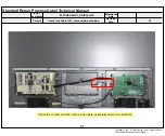
Страница 47: ...mptom Content A6 A6 Standard Repair Process Detail Technical Manual Connection diagram A Video error _Vertical Horizontal bar residual image light spot As the part connecting to the external input check the screen condition by signal Established date Revised date Error symptom Content Copyright 2017 LG Electronics Inc All rights reserved Only for training and service purposes ...

Страница 48: ...1 reconnection condition A Video error_Color error Check the contact condition of the Link Cable especially dust or mis insertion Established date Revised date Error symptom Content Copyright 2017 LG Electronics Inc All rights reserved Only for training and service purposes ...

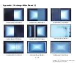
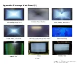
Страница 49: ...CNT Broken Solder defect CNT Broken Solder defect CNT Broken Solder defect CNT Broken Abnormal Power Section Solder defect Short Crack Abnormal Power Section Solder defect Short Crack Appendix Exchange Main Board 1 A 1 5 Copyright 2017 LG Electronics Inc All rights reserved Only for training and service purposes ...

Страница 50: ...normal Power Section Solder defect Short Crack Fuse Open Abnormal power section Noise GRADATION GRADATION Abnormal Display Appendix Exchange Main Board 2 A 2 5 Copyright 2017 LG Electronics Inc All rights reserved Only for training and service purposes ...

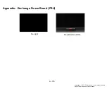
Страница 51: ...Appendix Exchange Power Board PSU No Light No picture Sound Ok A 3 5 Copyright 2017 LG Electronics Inc All rights reserved Only for training and service purposes ...

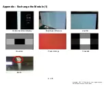
Страница 52: ...hange the Module 1 Vertical abnormal display Line Dim Crosstalk Crosstalk Press damage Brightness difference Burnt A 4 5 Copyright 2017 LG Electronics Inc All rights reserved Only for training and service purposes ...

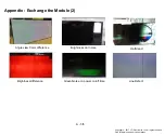
Страница 53: ...e 2 Angle view Color difference Brightness dot noise Half dead Green Noise on power on off time Line Defect Brightness difference A 5 5 Copyright 2017 LG Electronics Inc All rights reserved Only for training and service purposes ...

Страница 54: ...ck front Power Indicator B Power error _No power A8 Established date Revised date Error symptom Content A8 ST BY condition On or Off Power ON condition Turn Off Copyright 2017 LG Electronics Inc All rights reserved Only for training and service purposes ...

Страница 55: ...wer TV A9 Standard Repair Process Detail Technical Manual A9 Check the DC 12VM line for ST BY Voltage ST BY 7 8V Normal 12V Power To Main B d Power To Module P202 P201 B Power error _Off when on off whiling viewing Check power input Voltage ST BY 3 5V Error symptom Content Copyright 2017 LG Electronics Inc All rights reserved Only for training and service purposes ...

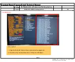
Страница 56: ... Repair Process Detail Technical Manual POWER OFF MODE checking method B Power error _Off when on off whiling viewing Entry method 1 Press the IN START button of the remote control for adjustment 2 Check the entry into adjustment item 3 Power On Off Status A10 ALL MODELS Error symptom Content Copyright 2017 LG Electronics Inc All rights reserved Only for training and service purposes ...

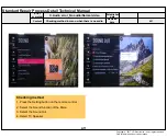
Страница 57: ...io Normal video A11 Established date Revised date Error symptom Content A11 Checking method 1 Press the Setting button on the remote control 2 Select the Sound function of the Menu 3 Select the Sound Out 4 Select TV Speaker Copyright 2017 LG Electronics Inc All rights reserved Only for training and service purposes ...

Страница 58: ...order when there is no audio Check the contact condition of or 20V connector of Main Board Measure the 20V input voltage supplied from Power Board If there is no input voltage remove and check the connector Connect the tester RX1 to the speaker terminal and if you hear the Chik Chik sound when you touch the GND and output terminal the speaker is normal 1 SPK_R _FT 2 SPK_R _FT 3 SPK_L _FT 4 SPK_L _...

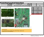
Страница 59: ... Check picture number and 2 Check the standby 3 5V on the terminal 22 pin 3 AS checking the Pre Amp IR LED light the power is in ON condition an Analog Tester needle should move slowly otherwise it s defective A13 IR EYE Sensor Pin Pin name 1 GND 2 KEY1 3 KEY2 4 3 5V_ST 5 GND 6 LOGO_LIGHT 7 IR 8 GND 9 EYE_SCL 10 EYE_SDA Checking order to check remote control Established date Revised date Error sym...

Страница 60: ... error Standard Repair Process Detail Technical Manual Motion Remote operation checking method D Function error A14 Checking order 1 Check BT Wifi cable condition between BT Wifi assy Main board 2 Check the 3 5V on the terminal 6 Wifi BT Front Wifi BT Rear Pin Pin name 1 GND 2 BT_RESET 3 N C 4 WOL WIFI_POWER_ON 5 GND 6 WIFI_DP 7 WIFI_DM 8 3 5V_WIFI Established date Revised date Error symptom Conte...

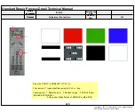
Страница 61: ...mage 3 MODULE error ADD BAR SCAN BAR 4 Video error Classification of MODULE or Main B D A15 Standard Repair Process Detail Technical Manual Adjustment Test pattern E Etc Established date Revised date Error symptom Content Error symptom Content Copyright 2017 LG Electronics Inc All rights reserved Only for training and service purposes ...

Страница 62: ......

Отзывы: