- 12 -
6. EDID(HDMI) Data Input
6-1. Required Test Equipment
(1) Jig for adjusting PC, DDC (PC serial to D-sub connection
device)
(2) S/W for writing DDC(EDID data write & read)
(3) D-sub terminal
(4) Jig for connecting EDID Cable(HDMI-DVI cable)
6-2. Adjustment Preparation and Setting of
Device
(1) Setup as in <Fig. 7> and turn on the PC & JIG.
(2) Operate the S/W for writing DDC(EDID data write & read)
(operated in DOS mode.)
6-3. Sequence of Adjustment
(1) Put the SET(or Digital Board) on the table and turn the
power on.
Connector the JIG for download to HDMI 1(#1) port.
(2) Input the product code, production week / year, serial
number (if it is not input, write “01”) to the S/W for writing
DDC.
(3) Open the first file [44/52SZ8D-UA]HDMI1_V1_1(93ED).DVI.
(4) Operate EDID Write command by pressing Function Key
F8.
(5) When “OK” letter appear, completed the Write.
(6) After connector the JIG for download to HDMI 2(#2) port,
open the second file [44/52SZ8D-UA]HDMI2_V1_1(697B).
DVI and operate as same above method.
7. CPLD Download Work
7-1. Required Test Equipments &
Preparation for Adjustment
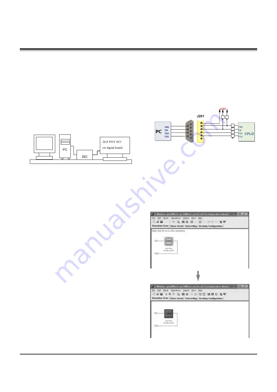
(1) Connect the PC and memory JIG as shown in <Fig. 8>.
(2) Turn on JIG MAIN POWER SW.
(3) Turn on the PC and moniter, operate the device
programming software.
7-2. Adjustment Sequence
(1) Once the program is running, [OPTION MODE
SELECTION] is displayed in the window.
Check the “Load configuration File(.cdf, .pdr)” in this
window and click the finish button
(2) When the screen displays the open window, select the
suitable file(*.cdf) according to model.
(3) IC figure is change to green by clicking it.
(Refer to <Fig. 9>)
ADJUSTMENT INSTRUCTIONS
<Fig. 7> Device Setting Diagram for Input EDID(HDMI) Data
<Fig. 8 > How to connect the MEMORY JIG and PC
<Fig. 9> CPLD DOWNLOAD PROGRAM
Содержание 52SZ8D
Страница 19: ... 18 BLOCK DIAGRAM ...
Страница 20: ... 19 BLOCK DIAGRAM ...
Страница 36: ......
Страница 37: ......
Страница 38: ......
Страница 39: ......
Страница 40: ......


