- 10 -
ADJUSTMENT INSTRUCTIONS
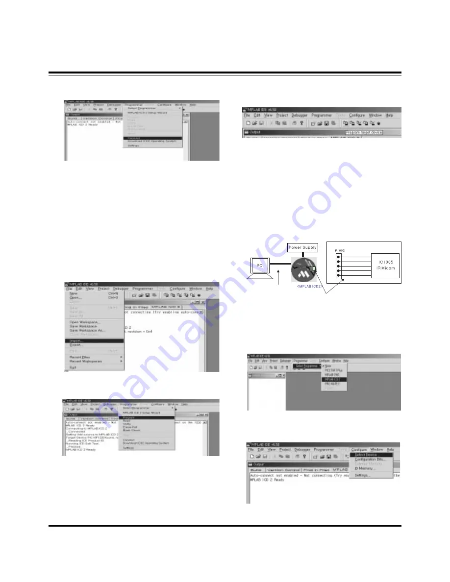
(4) Select "Programmer -> Connect".
When connected with the Micom, the display message on
the Output window appears as below.
(5) Select "File -> Import", select the Work HEX file and open.
(6) Select "Programmer -> Program".
(7) Download is executed and about 5 seconds later, the
"Programming succeeded" message is displayed on the
Output window and the Download process is ended.
(8) The execution of process (6) is convenient when using the
short-cut icon.
5. Gemstar IR Micom Download
5-1. Preparation for Adjustment
(1) As shown below, connect the MPLAB ICD2 equipment, PC
and Digital Connector.
(2) Turn on the MPLAB ICD2 POWER Supply.
(3) After turn on the PC and MONITOR, select the ‘MPLAB
IDE’ from the screen.
5-2. Adjustment Sequence
(1) When the program is executed, select the MPLAB ICD2
from "Programmer -> Select Programmer" .
(2) Select "Configure -> Select Device".
+13V
+5V
GND
Data
Clock
<Digital Board>
Connect the MPLAB ICD2 and connector of Digital Board
Connect the RS-232 or USB Cable
Connecting to MPLAB ICD 2
...Connected
Setting Vdd source to MPLAB ICD 2
Target Device PIC18F1220 found, revision = 0x4
...Reading ICD Product ID
Running ICD Self Test
...Passed
MPLAB ICD 2 Ready
Содержание 50PX5D
Страница 18: ... 18 PRINTED CIRCUIT BOARD MAIN DIGITAL TOP ...
Страница 19: ... 19 PRINTED CIRCUIT BOARD MAIN DIGITAL BOTTOM ...
Страница 20: ... 20 PRINTED CIRCUIT BOARD MAIN ANALOG TOP ...
Страница 21: ... 21 PRINTED CIRCUIT BOARD MAIN ANALOG BOTTOM ...
Страница 22: ... 22 PRINTED CIRCUIT BOARD SIDE A V INDEX TOP INDEX BOTTOM POWER LED TOP CONTROL SPDIF TOP SPDIF BOTTOM ...
Страница 23: ... 23 BLOCK DIAGRAM ...
Страница 36: ......
Страница 37: ......
Страница 38: ......
Страница 39: ......
Страница 40: ......
Страница 41: ......


