- 24 -
LGE Internal Use Only
Copyright©2008 LG Electronics. Inc. All right reserved. Only for training and service purposes
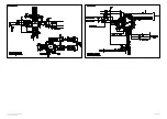
EXPLODED VIEW
280
290
230
520
400
590
910
307
120
306
560
570
571
561
302
303
305
300
304
200
240
901
900
250
209
208
201
204
207
A2
205
206
580
202
203
301
401
A21
Страница 1: ...PLASMA TV SERVICE MANUAL CAUTION BEFORE SERVICING THE CHASSIS READ THE SAFETY PRECAUTIONS IN THIS MANUAL CHASSIS PE81A MODEL 50PG60D 50PG60D GE website http biz LGservice com Internal Use Only ...
Страница 2: ... Electronics Inc All right reserved Only for training and service purposes CONTENTS CONTENTS 2 SAFETY PRECAUTIONS 3 SPECIFICATION 4 ADJUSTMENT INSTRUCTION 6 TROUBLE SHOOTING 13 BLOCK DIAGRAM 22 EXPLODED VIEW 24 SVC SHEET PRINTED CIRCUIT DIAGRAM ...
Страница 3: ...by it s Neck Leakage Current Cold Check Antenna Cold Check With the instrument AC plug removed from AC source connect an electrical jumper across the two AC plug prongs Place the AC switch in the on position connect one lead of ohm meter to the AC plug prongs tied together and touch other ohm meter lead in turn to each exposed metallic parts such as antenna terminals phone jacks etc If the exposed...
Страница 4: ...M 5 The receiver must be operated for about 20 minutes prior to the adjustment V Test Method 1 Performance LGE TV test method followed 2 Demanded other specification Safety CE IEC specification EMC CE IEC V General Specification 50 Module Display Screen Device Aspect Ratio PDP Module Operating Environment Storage Environment Input Voltage 1 2 3 4 5 6 No Item Specification Remark 50 Wide Color Disp...
Страница 5: ... Input 1EA Component Input 1EA RGB Input 1EA HDMIInput 4EA Audio Input 3EA 1 2 3 4 5 6 7 8 9 No Item Specification Remark Singapore South Africa 1 PAL BG 2 DVB T ID TV Analog Upper Heterodyne Digital COFDM PAL SECAM NTSC PAL SECAM NTSC Y Cb Cr Y Pb Pr RGB PC HDMI DTV SOUND PC Audio Component AV 4System PAL SECAM NTSC PAL60 4System PAL SECAM NTSC PAL60 L R Input V Model Specification ...
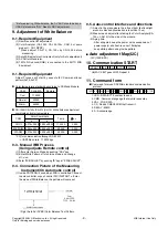
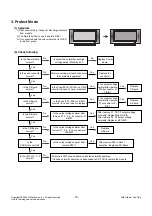
Страница 6: ...put the Video Signal 7 Color Bar signal into AV3 2 Set the PSM to Dynamic mode in the Picture menu 3 Press IN START key on R C for adjustment 4 Press the G Vol key to operate the set then it becomes automatically 5 Adjustment of Component 5 1 Standard Equipment 802F Pattern Generatorr Master Pattern Generator MSPG 925 etc or same product 5 2 Required Equipment O Remote controller for adjustment O ...
Страница 7: ...ress VOL key on Channel Recover 9 POWER PCB Assy Voltage Adjustments Va Vs Voltage adjustments 9 1 Test Equipment D M M 1EA 9 2 Connection Diagram for Measuring refer to Fig 4 9 3 Adjustment Method 1 Va Adjustment 1 After receiving 100 Full White Pattern HEAT RUN 2 Connect terminal of D M M to Va pin of P811 connect terminal to GND pin of P811 3 After turning RV901 voltage of D M M adjustment as s...
Страница 8: ...DMI 8 5 EDID DATA 1 Analog RGB Detail EDID Options are below 1 2 3 4 5 1 1 Product ID 2 2 Serial No Controlled on production line 3 3 Month Year Controlled on production line ex Monthly 03 03 Year 2006 10 4 4 Model Name Hex 5 5 Checksum Changeable by total EDID data 2 HDMI Detail EDID Options are below 1 2 3 4 5 6 1 1 Product ID 2 2 Serial No Controlled on production line 3 3 Month Year Controlled...
Страница 9: ...ace and directions 1 Adjust in the place where the influx of light like floodlight around is blocked illumination is less than 10ux 2 Measure and adjust after sticking the Color Analyzer CA 100 CA210 to the side of the module 3 Aging time After ajing start keep the power on no suspension of power supply and heat run over 15minutes keep white pattern using inside pattern V Auto adjustment Map I2C I...
Страница 10: ... it is produced in production line because serial number D L is mandatory by D book 4 0 14 Set Information Serial No Model name Option Table 14 1 Setting up Tool Option1 2 After setting white balance this is set Setting Press ADJ Key in the Adjust remocon 1 Press ADJ Key in the R C for adjustment 2 Insert Option value by a number key 3 Press the Enter Button 14 2 Check the serial number Model Name...
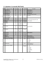
Страница 11: ...EB 20 30 90 92 16 18 1A 80 82 84 10 12 F1 F2 F3 F4 00 00 00 00 00 00 00 00 00 00 00 cool 01 medium 02 warm 00 cool 01 medium 02 warm 00 cool 01 medium 02 warm 00 00 00 00 00 00 00 00 00 00 00 00 00 data 00 00 64 00 64 00 64 00 64 00 80 00 80 00 80 00 7F 00 7F 00 7F 00 3F 00 64 02 0 1 2 3 00 FF 0 10 20 30 40 60 90 Factory mode on Factory mode off EEPROM All clear EEPROM Read EEPROM Write by some va...
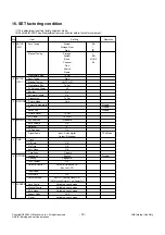
Страница 12: ...ce Off Key Lock Off On Set ID 1 Factory Reset OK ISM Method Normal Low Power Off Variable by each mode Variable by each mode Variable by each mode 16 9 Variable by each mode Disable Disable Disable DTV Mode Disable BG 1 G 1 BG V UHF 69 Item Setting No Remarks SETUP Auto Tuning ATV Manual Tuning Programme Edit SETUP Auto Tuning DTV Manual Tuning Programme Edit 5V Antenna Power Booster Software Upda...
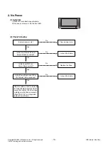
Страница 13: ...Monitor signal come out Yes 7 Check the VSC Vs ON signal Doesn t the high tension output come out Doesn t the VSC signal Vs ON come out Yes Yes Does high tension output voltage Drop occur When the Y B D Module input connector is removed does output voltage drop occur When the Y Z B D Module input connector is remove does Power Board hightension output voltage Drop occur Yes No No 9 Check the Power...
Страница 14: ... Spec SC101 P813 P811 P812 AC INLET MAIN BOARD PDP MODULE AC NC AC YH396 03 16V GND 12V GND 5VSC 5VSC GND GND 5V_MNT RL_ON M5V_ON M5V_ON GND GND GND GND 5V_MNT AC_DET RL_ON VS_ON M5V_ON AUTO_GND SMH200 22P Vs Vs NC GND GND Va Va GND M5V M5V YH396 10P Vs Vs NC GND GND Va Va GND M5V M5V YH396 10P 1 2 3 4 5 6 7 8 9 10 11 12 13 14 15 16 17 18 19 20 21 22 Description NO ...
Страница 15: ...ug in power cord Plug in power cord Yes No Is the Line Filter and Power Board Cable connected Connect the Cable Yes No Is the Fuse F101 on Power Board normal Replace the Fuse Yes No Is the Power Board and 13P of VSC Board Cable connected Connect the Cable Yes No After the cable connect is removed to Power Board except the SC101 connection cable the AC voltage marking is authorized on manual When S...
Страница 16: ... Ctrl B D Yes No Yes Is the Y Board normal Is the output voltage normal after remove P103 connector of Y B D Is the Fuse FS101 FS102 on Y B D normal In case of open is replace Yes No Yes Yes Replace Z Board Is the Z Board normal Is the output voltage normal after remove P1 connector of Z B D Is the Fuse FS1 FS2 on Z B D normal In case of open is replace Yes No Yes Is the X Board normal Is the outp...
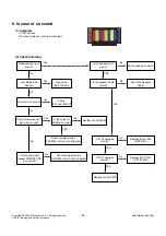
Страница 17: ...normal Is the VAVS on Check the PDP Module Yes No YES Yes Reconnect the LVDS cable in P800 No Is the IC700 FLI8548 Output normal Replace the VSC No NO Replace the Power board Is output the normality Low High voltage except stand by 5V NO 4 No Raster 1 Symptom 1 No OSD and image occur at screen 2 It maintains the condition where the front LED is green 2 Check following ...
Страница 18: ...isplayed 1 Symptom 1 LED is green 2 The minute discharged continuously becomes Accomplished from module 2 Check following Is the LVDS cable normal Is the VSC Board normal Is the LVDS cable connected Re insert the Cable inserts Yes No No Yes Does the FIL8548 IC IC700 Operates Replace FIL8548 IC IC700 No Is the Ctrl Board of Module normal Replace Ctrl B D No No Yes Replace hte VSC B D Replace the ca...
Страница 19: ...e case of becomes unusual display from side S video AV mode Is the Tuner normal Is the CXA2069Q normal Is the Tuner Cable connected Re insert the Cable Yes No No Yes Is the FIL8548 normal Replace the Tuner No Is the Input voltage IIC Communication and CVBS output normal Yes Is the Input voltage IIC Communication normal No Replace the IC No Is normal the Input voltage IIC Communication No Block A R...
Страница 20: ...lay from SCART1 mode 8 In the case of becomes unusual display from SCART2 mode Is theR G B input and H V Sync of the J1100 normal Check the input source No Is the HDMI IC1000 normal Yes Same as Block A Is the Input and Output signal IIC Communication normal No Is the Video input od A V Jack J1200 normal Yes Same as Block A Check the input source No Replace the IC No Is the Video input od A V Jack ...
Страница 21: ...to circuit diagram Yes Only specific input except HDMI DTV RF is no sound Check the signal before CAX2069 refer to circuit diagram No No YES Only RF is no sound Check the Tuner IN OUT Yes No YES Only AV component PC input is no sound Is the output of CXA2069 normal Yes No IC1300 operates normal Replace the IC1300 MSP4450 No IC1301 operates normal Replace the IC1301 NTP 3000A No YES Replace the VSC...
Страница 22: ...3000A AudioIC 18V V L R Y C Component 1 Y Pb Pr L R RF IN 1 8V 3 3V 5V D A Synthesis Tuner TDFV G135D S PDIF RGB 24bit SD HD CVBS DTVL ROUT TMDS CEC 1 2 COMP Y Pb Pr PC R G B HV_SYNC SCART R G B FB I2S SIDE A V SIF AM_AUDIO COMP PCR LIN AV R LOUT TVR L OUT TVR LOUT TU_MAIN V Y C L R MAIN_V Y C OUT LVDS Sound Signal Video Signal Sound Video Signal RX TD Signal Etc Signal Hsync Vsync DE HDMI1 1 8 V ...
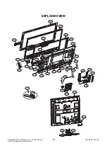
Страница 23: ... LG Electronics Inc All right reserved Only for training and service purposes EXPLODED VIEW 280 290 230 520 400 590 910 307 120 306 560 570 571 561 302 303 305 300 304 200 240 901 900 250 209 208 201 204 207 A2 205 206 580 202 203 301 401 A21 ...
Страница 24: ...LGE Internal Use Only Copyright 2008 LG Electronics Inc All right reserved Only for training and service purposes ...
Страница 25: ...LGE Internal Use Only Copyright 2008 LG Electronics Inc All right reserved Only for training and service purposes ...
Страница 26: ...LGE Internal Use Only Copyright 2008 LG Electronics Inc All right reserved Only for training and service purposes ...
Страница 27: ...LGE Internal Use Only Copyright 2008 LG Electronics Inc All right reserved Only for training and service purposes ...
Страница 28: ...Apr 2008 Printed in Korea P NO MFL42198302 ...