Checking order
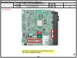
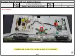
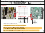
1.Check IR cable condition between IR & Main board.( Check picture number
①
and
②
)
2.Check the standby 3.5V on the terminal 22 pin (
③
)
3.AS checking the Pre-Amp(IR LED light) , the power is in ON condition, an Analog Tester
needle should move slowly, otherwise, it’s defective.
Standard Repair Process Detail Technical Manual
Remote control operation checking method
D. Function error
A22
Established
date
Revised
date
Error
symptom
Content
A22
②
③
1
+3.5V
2
WIFI_DM
3
WIFI_DP
4
GND
5
WOL_ON
6
3.5V
7
COMBO_RESET
8
GND
9
COMBO_WAKEUP_DEVICE
10
COMBO_WAKEUP_HOST
11
GND
12
GND
13
NC
14
NC
15
NC
16
EYE_SDA
17
EYE_SCL
18
GND
19
IR
20
LED
21
GND
22
3.5V
23
KEY2
24
KEY1
25
GND
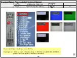
Checking order to check remote control
IR & Standby light Rear
IR
Eye
LED
IR & Standby light Front
<ALL MODELS>
Содержание 43UJ6200-UA
Страница 11: ...AR1 ARC1 700 200 570 571 120 501 510 901 902 400 521 540 A10 530 500 LV1 LV2 ...
Страница 15: ...LCD TV Repair Guide Applicable Model 43 49 55 65UJ6200 UA ...
Страница 19: ...Interconnection 1 2 3 1 2 3 4 Main PCB PSU PANEL FFC Cable Wifi Only Local Key IR ASSY 4 5 4 5 SPEAKER 65UJ62 ...
Страница 20: ...TROUBLE SHOOTING GUIDE ...
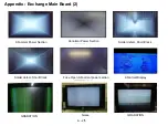
Страница 52: ...Appendix Exchange Power Board PSU No Light Dim Light Dim Light Dim Light No picture Sound Ok A 3 5 ...
Страница 62: ......

